


14
INSTALLATION AND CONNECTIONS
Installation and Connections
After unpacking the unit, and placing it on a solid
surface capable of supporting its weight, you will
need to make the connections to your audio and
video equipment.
Audio Equipment Connections
We recommend that you use high-quality inter-
connect cables when making connections to
source equipment and recorders to preserve the
integrity of the signals.
When making connections to audio source
equipment or speakers it is always a good
practice to unplug the unit from the AC wall
outlet. This prevents any possibility of
accidentally sending audio or transient signals to
the speakers that may damage them.
1. Connect the front speaker outputs
B
to the
respective speakers.
Cables that are run inside walls should have the
appropriate markings to indicate listing with any
appropriate testing agency standards. Questions
about running cables inside walls should be
referred to your installer or a licensed electrician
who is familiar with the applicable local building
codes in your area.
When connecting wires to the speakers, be cer-
tain to observe proper polarity. Note that the
positive (+) terminal of each speaker connection
now carries a specific color code. However, most
speakers will still use a red terminal for the pos-
tive (+) connection. Connect the “negative” or
“black” wire to the same terminal on both the
receiver and the speaker.
We also recommend that the length of cable
used to connect speaker pairs be identical.
For example, use the same length piece of
cable to connect the front-left and front-right
speakers, even if the speakers are a different
distance from the HS controller.
2. Connections to the subwoofer are made via a
line level audio connection from the
Subwoofer Output
7
to the line-level SUB
input (purple) of the subwoofer. Connect at the
same time the
Subwoofer Trigger Output
F
to the Trigger Input of the subwoofer.
3. Connect the supplied FM antenna to the
FM
(75 ohm)
connection
5
. The FM antenna may
be an external roof antenna, an inside powered
or wire lead antenna or a connection from a
cable system. Note that if the antenna or con-
nection uses 300-ohm twin-lead cable, you
should use a 300-ohm-to-75-ohm adapter to
make the connection.
Video Equipment Connections
Video equipment is connected in the same man-
ner as audio components. Again, the use of high-
quality interconnect cables is recommended to
preserve signal quality.
Connecting the TV and optional
components
NOTE:
To be able to listen to the sound of a live
TV show through the loudspeakers of your HS
system you need a connection between the audio
output of your TV and the HS controller: to achieve
this when using the supplied SCART cable, you
don’t need to connect any additional wires – the
SCART cable transports audio and video signals in
both directions. But when using the HDMI,
Component, S-Video or composite jacks you need
to connect the audio output of your TV set with
the
TV AUDIO IN
K
on the back of your HS
controller. If your TV has a digital audio output, it is
recommended to use that one over the analog
audio output. Connect the digital output of your
TV to the
DIGITAL IN
89
on the back of your
HS Controller.
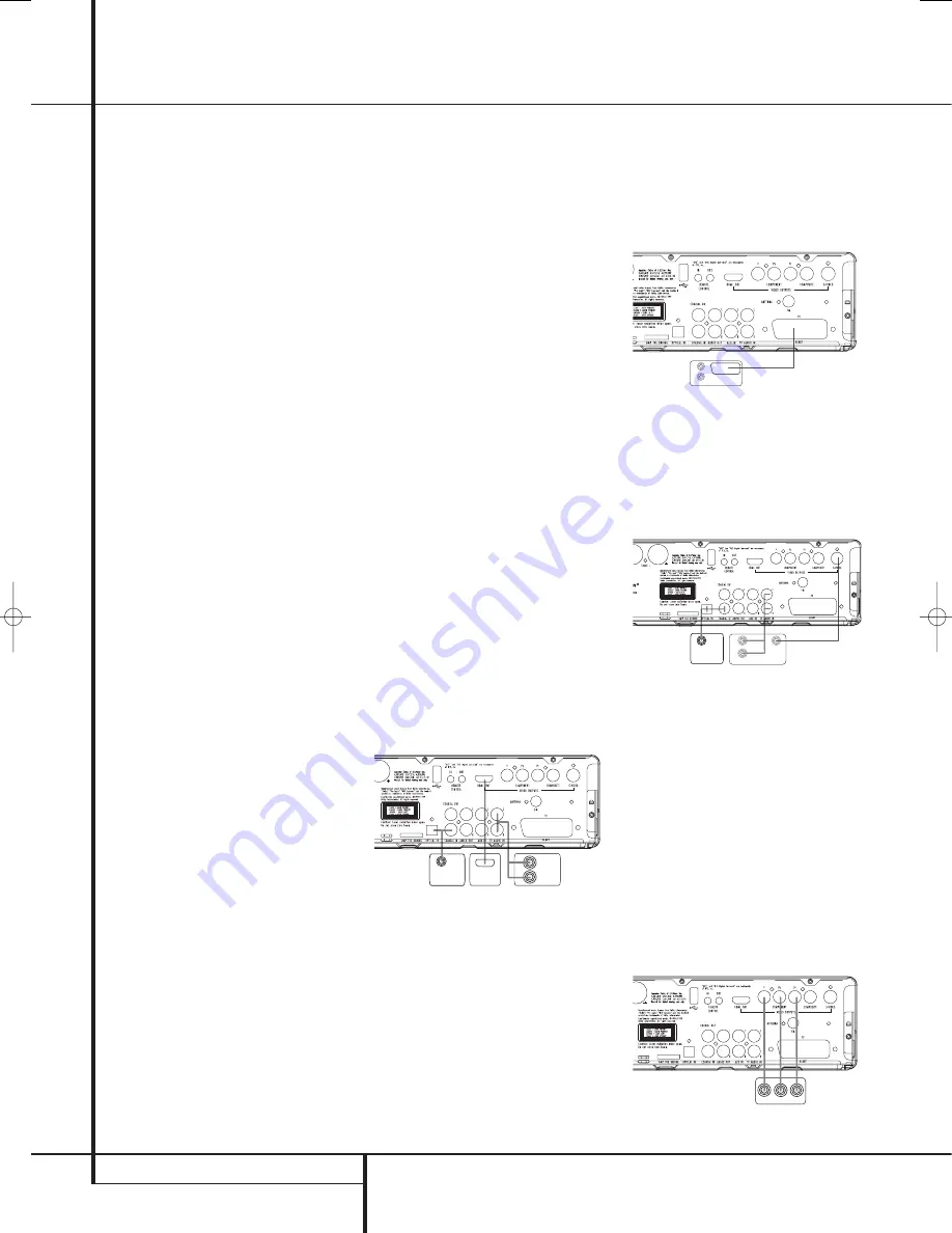
HDMI Connection
If your TV set is equipped with an HDMI input, we
suggest you use the HDMI connection to connect
your HS system and your TV. It will allow you to
watch your DVD's in the best possible picture
quality. Most LCD, Plasma and video projectors
have such an HDMI input nowadays. Connect the
HDMI Output
H
to the HDMI Input of your
video device.
The HDMI wire does not transport audio signals
from the TV to the HS, thus you need an additional
audio connection (see note above).
If your TV set does not have an HDMI Input, please
follow one of the steps below to connect it to your
HS system or other video components.
TV Connection (method 1)
– using SCART cable (included)
To view the video from DVD discs on your TV set,
connect the SCART TV Out jack
3
of the HS
system to the SCART In jack of your TV set. The
audio connection runs through the same cable
(see note above).
TV Connection (method 2)
– using S-Video cable (not included)
If your TV set has an S-Video input jack you can
connect your TV to the S-Video out jack
1
on the
back of the HS controller. S-Video wires don’t
transport audio signals, thus you need an
additional audio connection (see note above).
TV connection (method 3) – using
composite video (cable not included)
If your TV set has neither S-Video nor SCART
input jacks, connect the Video Out jack
0
of
the HS to the Video In jack of your TV set. The
composite wire also doesn’t transport audio
signals, thus you need to make additional
connections (see earlier note).
Component Video Connection (method 4)
If the video display has component video inputs,
connect the Component Video Outputs
2
on
the HS 250 to the corresponding input jacks on
your television. If you are using a progressive
scan television or projector, you must also
change the Scan Type in the DVD player's Video
Set-Up Menu from ”Interlaced” to
”Progressive”.
COMPONENTS IN
TV SET
AUDIO OUT
S-VIDEO IN
DIGITAL OUT
TV SET
AUDIO OUT
HDMI IN
AUDIO OUT
DIGITAL OUT
34138_HS250_UK 18/09/07 13:58 Side 14


