background image

28

INITIAL SETUP

Resolution to Display

: This setting reflects the video output resolution, 

which is dependent upon the capabilities of the video display.

If the display is connected to the AVR’s HDMI Output, the two devices will 


communicate with each other, and the AVR will automatically select the 
best available video output resolution.

If the display is connected to the AVR’s Component Video Outputs, there is 


no automatic detection of the display’s capabilities, and the video output 
resolution must be manually adjusted to match the display’s capabilities 
(which may be obtained from the display’s manual or its manufacturer’s 
Web site).

If the display is connected to the AVR’s Composite Monitor Output, the 


video output resolution must be set to 576i (the factory default) to view 
any content, including the AVR’s own menus.

Adjust the resolution by pressing the front-panel Resolution Button and 
using the 

KL

 Buttons until the correct setting appears in the front-panel 

Message Display. For composite video, the correct setting is 576i. For 
component video, it is the highest resolution where a picture is visible. You 
will be prompted to accept or cancel the resolution change; the CANCEL 
message will appear on the front panel. Press the 

L

 Button to view the 

ACCEPT option and then press the OK Button.

NOTE

: When the display has a DVI input which is connected to the AVR 

using an HDMI-to-DVI adapter, the picture will be distorted or blank if the 
display is not HDCP-compliant. In that case, a different video connection 
must be used (component or composite).

Resolution From Source

: Informational only. Indicates the resolution of 

the video output by the source device.

HDMI Bypass

: When an HDMI source signal is in use and the system 

includes an HDMI-capable display, the HDMI Bypass mode passes the source 
signal directly to the HDMI Output, bypassing all video processing within 
the AVR, including video output resolution adjustment. To allow the AVR to 
process all video, including “blending” the source video with its on-screen 
messages and menus so that you may adjust the AVR without missing any 
portion of the program, turn this setting off. When the HDMI Bypass mode 
is on, it is not possible to “blend” the video source signal with the AVR’s 
on-screen menus. When any remote or front-panel buttons are pressed, the 
AVR will momentarily exit HDMI Bypass mode and display the on-screen 
menu on a black background. After the menu is cleared from the screen, 
either by timing out or when the Back/Exit Button is pressed, the AVR will 
return to HDMI Bypass mode.

Change Name

: Change the display name for your source, which is useful if 

your source’s device type is different from the available source names. Select 
this line and use the 

KL

 Buttons to scroll forward or reverse through the 

alphanumeric characters. When the desired character appears, use the 

N


Button to move the cursor to the next position. Move the cursor again to leave 
a blank space. When you have finished, press the OK Button. The name will 
appear on the front panel and next to its original name, e.g., DVD, throughout 
the on-screen menu system. To clear the entry without making any changes, 
scroll to the blank character before “A”.
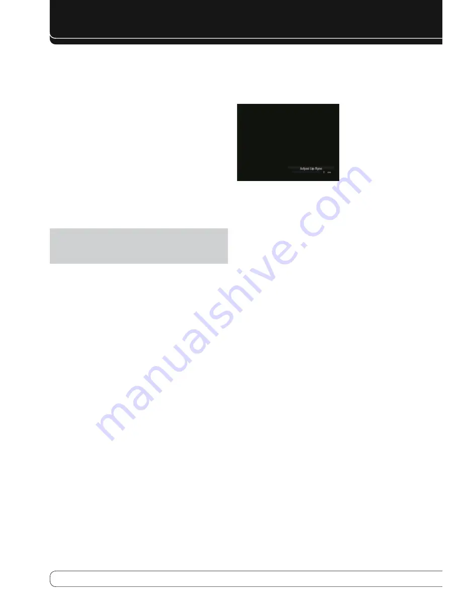
Adjust Lip Sync

: Resynchronizes the audio and video signals from a 

source to eliminate a “lip sync” problem. Lip sync issues can occur when the 
video portion of a signal undergoes additional processing in either the source 
or the video display. The Lip Sync adjuster appears by itself, enabling you to 
view the video while listening to the audio. Use the 

M N

 Buttons to delay the 

audio by up to 180ms. See Figure 25.

Figure 25 – Adjust Lip Sync

Audio Auto Polling

: Used when both analog and digital audio 

connections are made. When no digital signal is present, the AVR will 
automatically switch to the analog audio input.

This can be useful for older cable television systems that broadcast channels 
in both analog and digital audio.

If an analog audio connection was made, select it here. If not, choose the Off 
setting, and the AVR will always use the digital audio connection.

Zone 2 Audio

: Determines the audio source for the multizone system 

remote zone. Select the analog audio input the source is connected to. Digital 
audio is not available to the multizone system.

Press the Back/Exit Button, then return to the Setup Source line of the Main 
Menu to configure the next source. When you have finished, press the Back/
Exit Button to clear the menus from view.

You are now ready to begin enjoying your new receiver!

Summary of Contents for HARMAN/KARDON AVR 460

Page 1: ...AVR 460 AVR 360 AUDIO VIDEO RECEIVERS OWNER S MANUAL Basic Functions...

Page 2: ...er supply cord shall remain readily operable 17 Do not expose batteries to excessive heat such as sunshine fire or the like 18 The lightning flash with arrowhead symbol within an equilateral triangle...

Page 3: ...e finish cleaning materials used and normal heat and vibration caused by the use of the product or other factors We recommend that caution be exercised in choosing an installation location for the com...

Page 4: ...VR 460 AVR 360 29 Volume Control 29 Dolby Volume 30 Mute Function 30 Sleep Timer 30 Audio Effects 30 Video Modes 30 Headphones 30 Source Selection 31 Using the Radio 31 RDS Functions 32 Recording 32 U...

Page 5: ...become more familiar with its features and their operation If you have any questions about this product its installation or its operation please contact your Harman Kardon retailer or custom installer...

Page 6: ...lor user interface and setup menu generated in high definition video Two line dot matrix front panel display Color coded connections Programmable learning eight device main remote control includes AVR...

Page 7: ...for the current source Resolution Press this button to access the AVR s video output resolution setting 576i 576p 720p 1080i or 1080p IMPORTANT NOTE If the AVR s video output resolution is set higher...

Page 8: ...a digital camera or game console to these jacks Use only one type of audio and one type of video connection Note The AVR s menus refer to these jacks as the Optical Front Coaxial Front Composite Fron...

Page 9: ...e AVR Remote IR Carrier Output AVR 460 only This output is similar in function to the Remote IR Output with the difference that this jack outputs the full infrared signal as received by the AVR s IR s...

Page 10: ...the source to one of the sets of component video inputs Do not make any other video connections to that source Component Video Monitor Outputs If you are using one of the Component Video Inputs and yo...

Page 11: ...h only the codes specific to each brand and model changing depending on which product code is programmed The AUX and Cable SAT Source Selectors may be used for multiple device types Other Source Selec...

Page 12: ...me The surround mode will change when the menu line is highlighted To change the surround mode for the selected category press the OK Button when the menu line is highlighted and select one of the ava...

Page 13: ...f the remote Make sure to observe proper polarity by matching the and symbols on the batteries to the symbols printed inside the compartment The following explanations describe the buttons that are no...

Page 14: ...he surround back channels power loudspeakers located in another room Many people expect the surround speakers to play as loudly as the front speakers Although all of the speakers in the system will be...

Page 15: ...bass which require more power To obtain the best results most speaker manufacturers offer powered subwoofers that contain their own amplifier Usually a line level nonamplified connection is made from...

Page 16: ...l Audio Analog Audio Two channel analog connections require two cables one for the left channel white and one for the right channel red These two cables are often attached to each other See Figure 7 F...

Page 17: ...nce Y and two sub sampled color signals Pb and Pr that are transmitted using three separate cables See Figure 11 Component video cable Y Green Pb Blue Pr Red Figure 11 ComponentVideo If it s available...

Page 18: ...akers are placed 90 degrees from the center speaker directly to either side of the listening position The surround back left and right speakers are placed 150 degrees from the center speaker or direct...

Page 19: ...programming control codes into the handheld remote and as explained on page 23 you may reassign any Source Selector s device type Any audio or video source may be connected to any matching jack on the...

Page 20: ...ly record from their direct cable or satellite television signals to the AVR s recording outputs Decide which audio inputs to connect to each source 6 Assign only one unique digital audio input to eac...

Page 21: ...minal on the AVR also colored black and the positive terminal on the speaker usually red to the positive terminal on the AVR color varies by channel see Table 1 on page 15 If you have a subwoofer conn...

Page 22: ...r distribute the audio signal to a single pair of speakers or to several pairs placed in different rooms The Zone 2 Audio Outputs offer the benefit of 7 1 channel audio in the main room simultaneously...

Page 23: ...Sources Into the Remote The AVR 460 AVR 360 remote may be programmed to control many brands and models of DVD players cable boxes satellite receivers the Harman Kardon DMC 1000 digital media center an...

Page 24: ...the four Soft key Buttons Channel Up Down Volume Up Down Mute and the Transport Controls including Record Press and hold the source button until the Source Selector flashes three d times Program addi...

Page 25: ...evices should be connected You should be able to turn on the receiver and view the main menu when you press the Setup Button If necessary reread the Installation Section and the beginning of this sect...

Page 26: ...nect the subwoofer until after running the EzSet EQ process The test will begin and the screen shown in Figure 23 will appear Maintain silence during the EzSet EQ configuration Figure 23 EzSet EQ in P...

Page 27: ...d to and select that input here If both analog and digital audio connections were made select the digital input here and select the analog input at the Audio Auto Polling and Zone 2 Audio lines below...

Page 28: ...the HDMI Bypass mode is on it is not possible to blend the video source signal with the AVR s on screen menus When any remote or front panel buttons are pressed the AVR will momentarily exit HDMI Byp...

Page 29: ...m web site Dolby Volume The AVR 460 AVR 360 implements Dolby Volume processing which can improve the audio performance of the system by revealing subtle details even at normal home listening volumes O...

Page 30: ...P3 enhancement to improve performance Access these settings from the Audio Effects submenu as described in the Advanced Functions Manual It is recommended that you leave the settings at their default...

Page 31: ...sages about the station or specifics of a musical selection and the correct time As more FM stations become equipped with RDS capabilities the AVR will serve as an easy to use center for both informat...

Page 32: ...d Unauthorized duplication of copyrighted materials is prohibited by federal law Using Docking Station The Bridge III is an optional dock that is compatible with most docking iPod models 4G and later...

Page 33: ...ed to the AVR 460 AVR 360 and the system is not in iPod Manual Mode the Now Playing screen will appear and display the play mode icon song title artist and album A graphic bar indicates the current pl...

Page 34: ...or Game mode depending on the source Virtual Surround When only two main speakers are present in the system Harman Virtual Surround may be used to create an enhanced soundfield that virtualizes the mi...

Page 35: ...er wires for shorts at receiver and speaker ends Amplifier is in protection mode due to internal problems Contact your local Harman Kardon service center No sound from surround or center speakers Inco...

Page 36: ...time Table A2 Source Setting Defaults Cable Sat DVD Media Server Radio TV Game AUX The Bridge Surround Modes Auto Select Logic 7 Movie Logic 7 Movie Logic 7 Movie Logic 7 Movie Logic 7 Movie Logic 7...

Page 37: ...4 4 kg Depth measurement includes knobs buttons and terminal connections Height measurement includes feet and chassis Features specifications and appearance are subject to change without notice TECHNI...

Page 38: ...8500 Balboa Blvd Northridge CA 91329 www harmankardon com 2009 Harman International Industries Incorporated All rights reserved Part No CQX1A1433Z...

Reviews: