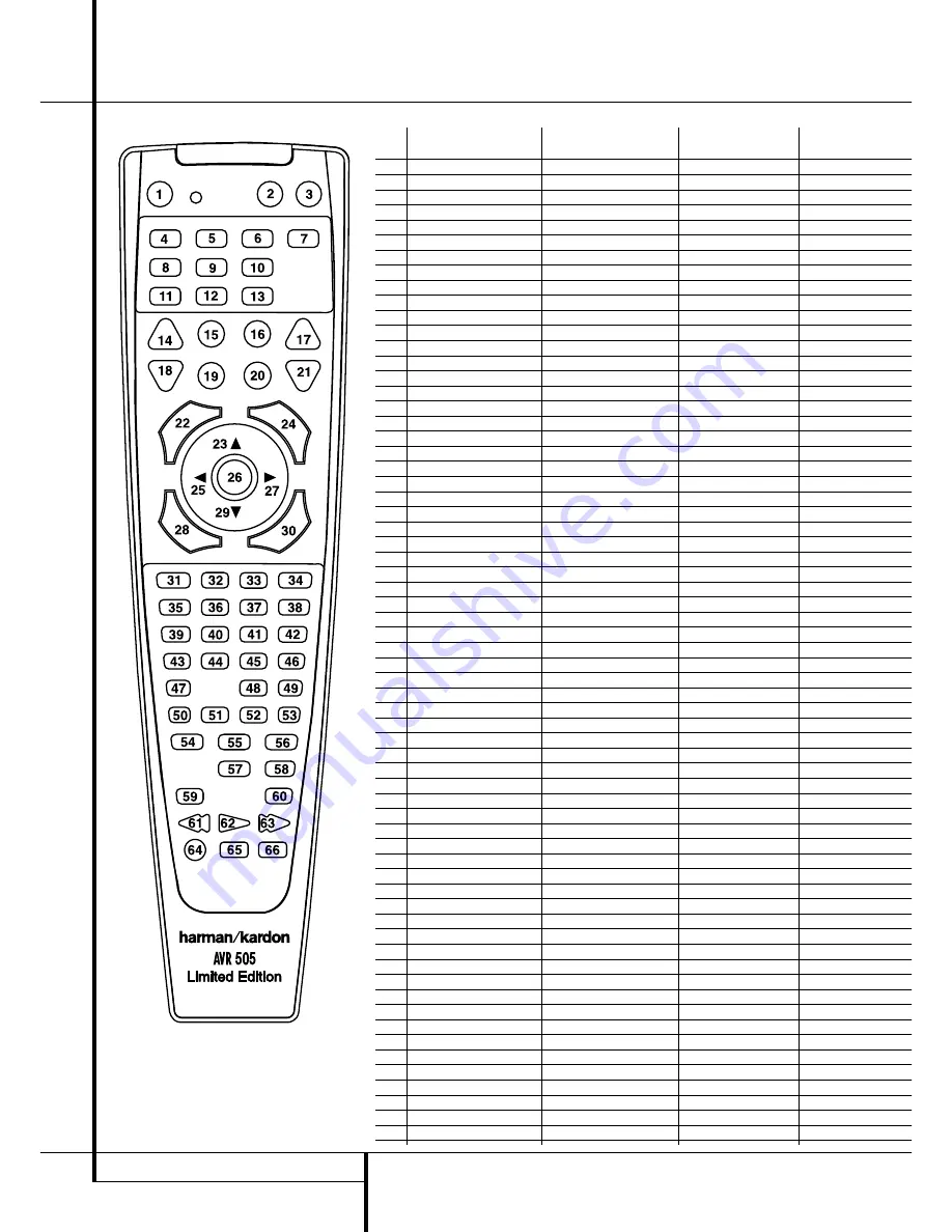
background image

30

FUNCTION LIST

Function List 

No.

Button Name

AVR Function

DVD

CD/CDR

1

Power On

Power On

Power On

Power On

2

Power Off

Power Off

Power Off

Power Off

3

Mute

Mute

4

AVR

AVR Select

5

DVD

DVD Input Select

DVD Select

6

CD

CD Input Select

CD Select

7

Tape

Tape Input Select

8

VID 1

Video 1 Select

9

VID 2

Video 2 Select

10

VID 3

Video 3 Select

11

DIM

DIM

12

AM/FM  

Tuner Select

13

6 CH Input Select

6 CH Input Selector

14

Sleep

Sleep

15

Test  

Test Tone

-/Input Select

16

TV

TV/DVD

-/CDP Select

17

Volume Up  

Volume Up

Volume Up

18

Surround Select

Surround Mode Select

-/CDR Select

19

Night

Night Mode Select

Subtitle on/off

20

Spare

21

Volume Down

Volume Down

Volume Down

22

Channel/Guide

Channel Trim

Title

23

Move/Adjust Up

Up

24

Speaker/Menu

Speaker Adjust

Menu

Intro/-

25

Left

26

Set

Set

Enter

27

Right

28

Digital/Exit

Digital Input Select

Open/Close

29

¤

Move/Adjust Down

Down

30

Delay/Prev. Ch.

Delay Adjust

Return

Open/Close

31

1

1

1

1

32

2

2

2

2

33

3

3

3

34

4

4

4

35

5

5

5

5

36

6

6

6

37

7

7

7

7

38

8

8

8

8

39

Tun-M

Tuner Mode

Chapter

Repeat

40

9

9

9

9

41

0

0

0

0

42

Memory

Memory

Audio

Time/CDR Display

43

Tune Up

Tune Up

44

Direct

Direct Tuner Entry

Angle

Random

45

Clear

Clear

Clear

Clear

46

Preset Up

Preset Tune Up

Slow Forward

+10/-

47

Tune Down

Tune Down

-/Track Increment

48

RDS

RDS Select

Disc Skip

Disc Skip

49

Preset Down

Preset Tune Down

Slow Rev

50

M1

51

M2

52

M3

53

M4

54

Dolby

Dolby Mode Select

55

DTS Sur

DTS 5.1 Select

56

DTS Neo:6

DTS Neo:6 Select

57

Logic 7 

Logic 7 Select

58

Stereo

Stereo Select 

59

Skip Down

Skip – 

Skip –

60

Skip Up

Skip +

Skip +

61

Rewind

R. Search

R. Search

62

Play

Play

Play

63

Fast Forward

F. Search

F. Search

64

Record

-/Record

65

Stop

Stop

Stop

66

Pause

Pause

Pause

Summary of Contents for AVR 505 LIMITED EDITION

Page 1: ...Limited Edition Audio VideoReceiver OWNER S MANUAL DIGITAL LOGIC 7 VID 1 DVD CD FMAM TAPE 6 CH VID 2 VID 3 PRO LOGIC 3 STEREO DSP 5 CH STEREO SURR OFF Surr Select Coaxial RDS Power for the Digital Rev...

Page 2: ...r Operation 26 RDS Operation 27 Programming the Remote 27 Programming the Remote with Codes 28 Programmed Device Function 28 Macro Programming 29 Volume Punch Through 29 Channel Control Punch Through...

Page 3: ...s are available In addition to providing a wide range of listening options the AVR 505 Limited Edition is easy to configure so that it provides the best results with your speakers and specific listeni...

Page 4: ...ain that proper space is provided both above and below the unit for ventilation If this product will be installed in a cabinet or other enclosed area make certain that there is sufficient air movement...

Page 5: ...ttons When you are establish ing theAVR s configuration settings use these buttons to select from the choices available as shown in the Main Information Display 6 Tone Mode Pressing this button enable...

Page 6: ...t right chan nels by as much as 10dB Set this control to a suitable position for your taste or room acoustics Volume Control Turn this knob clockwise to increase the volume counterclockwise to decreas...

Page 7: ...ed make connections to the AM and GND terminals in accordance with the instructions supplied with the antenna Video 1 Audio Outputs Connect these jacks to the RECORD INPUT audio jacks on a VCR or any...

Page 8: ...ice The power will remain on at this outlet regardless of whether the AVR is on or off in Standby pro vided that the Main Power switch 1 is on Note The total power consumption of all devices connected...

Page 9: ...s Transport Controls Skip Up Down Buttons RDS Select Button Preset Up Down Clear Button Memory Button Delay Prev Ch Button Speaker Select Spare Button Volume Up Down TV Video Selector Mute Dim Button...

Page 10: ...ation Note that this button is also used to tune channels when the TV VCR and SAT receiver is selected using the Input Selector 4 A Night Mode Press this button to activate the Night mode This mode is...

Page 11: ...utton is pressed with the Input Selector button 4 to begin the programming process See page 27 for more information on programming the remote NOTE As any of the remote buttons pressed is active with t...

Page 12: ...n area of 1 5 mm2 may be used for short runs of less than 4 m We do not recom mend that you use cables with an area less than 1mm2 due to the power loss and degradation in performance that will occur...

Page 13: ...a VCR connect the Out plugs to the Out jacks on the AVR Note that with some adapter types it may be just turned around If no signal is audible visible when the VCR is playing connect the Out plugs to...

Page 14: ...not shielded even with complete surround sets only the Center speaker may be Depending on the specifics of your room acoustics and the type of speakers in use you may find that imaging is improved by...

Page 15: ...log source except for the DVD input which has the Coaxial Digital Input 1 as the default with Logic 7 Music as the surround mode all speaker positions set to small and a subwoofer connected Before us...

Page 16: ...Set button E again and then use the buttons C on the remote or the Selector buttons 5 on the front panel to select the option that best describes your system based on the Surround speaker definitions...

Page 17: ...to the speaker group selection 5 Press the Buttons C on the remote or the Buttons 5 on the front panel again to select another speaker group either CENTER FREQ to adjust the crossover for the center c...

Page 18: ...st the delay time setting Note that the delay time is not adjustable for any other modes Due to the different distances between the listening position for the front channel speakers and the surround s...

Page 19: ...ers have been properly connected As the test noise circulates listen to make certain that the sound comes from the speaker position shown in the Main Information Display If the sound from a speaker lo...

Page 20: ...anel Video 3 Inputs may be used to connect a device such as a video game or camcorder to your home entertainment system on a temporary basis As the input source is changed the new input name will appe...

Page 21: ...n s patented VMAx mode No surround channels VMAx Far delivers a three dimensional sound space with the illusion of phantom speakers at the center and surround positions The VMAx N or Near Field mode s...

Page 22: ...in use In addition when a digital source is present the AVR will automatically select and switch to the correct mode Dolby Digital or DTS regardless of the mode that has been previously selected For...

Page 23: ...the number of channels present in the data An example of this type of display is 3 2 1 The first number indicates how many discrete front channel signals are present A 3 tells you that separate front...

Page 24: ...ed and adjust to accommodate it 4 When a Dolby Digital or DTS source is playing you normally may not be able to select some of the analog surround modes such as Dolby Pro Logic II Dolby 3 Stereo Hall...

Page 25: ...time all information must be reentered Tuner Operation The AVR s tuner is capable of tuning AM FM and FM Stereo broadcast stations and receiving RDS data Stations may be tuned manually or they may be...

Page 26: ...quires a strong enough signal for proper operation Program Search PTY An important feature of RDS is its capability of encoding broadcasts with Program Type PTY codes that indicate the type of materia...

Page 27: ...se a number of different combinations of codes so it is a good idea to make certain that not only does the Power control work but that the volume channel and transport controls work as they should If...

Page 28: ...erate check to see if another code set will work with more buttons Depending on the brand and product type used the functions listed in the Function List tables may not correspond with the function th...

Page 29: ...s the VID 1 VCR Input Selector button 4 and the Mute button at the same time Next release them and press the Volume Down button followed by the VID 2 TV Input Selector button 4 NOTE To remove the Chan...

Page 30: ...ust Menu Intro 25 Left 26 Set Set Enter 27 Right 28 Digital Exit Digital Input Select Open Close 29 Move Adjust Down Down 30 Delay Prev Ch Delay Adjust Return Open Close 31 1 1 1 1 32 2 2 2 2 33 3 3 3...

Page 31: ...u Menu Menu 25 Left Left Left Left 26 Set Enter Enter Enter Enter 27 Right Right Right Right 28 Digital Exit Exit Exit Exit Exit 29 Down Down Down Down 30 Delay Prev Ch Prev Channel Prev Channel Prev...

Page 32: ...1 is pushed into a live outlet Check to see if outlet is switch controlled Display lights but no sound Intermittent input connections Make certain that all input and speaker or picture connections are...

Page 33: ...nal to Noise Ratio 45dB Usable Sensitivity Loop 500 V Distortion 1kHz 50 Mod 0 8 Selectivity 10kHz 30dB Video Section Video Format PAL NTSC Input Level Impedance 1Vp p 75 ohms Output Level Impedance 1...

Page 34: ...250 Crossways Park Drive Woodbury New York 11797 www harmankardon com Harman Consumer International 2 route de Tours 72500 Ch teau du Loir France 08 2003 Harman Kardon Incorporated Part No CQE1A8654...

Reviews: