background image

31

AVR

Operating Your AVR

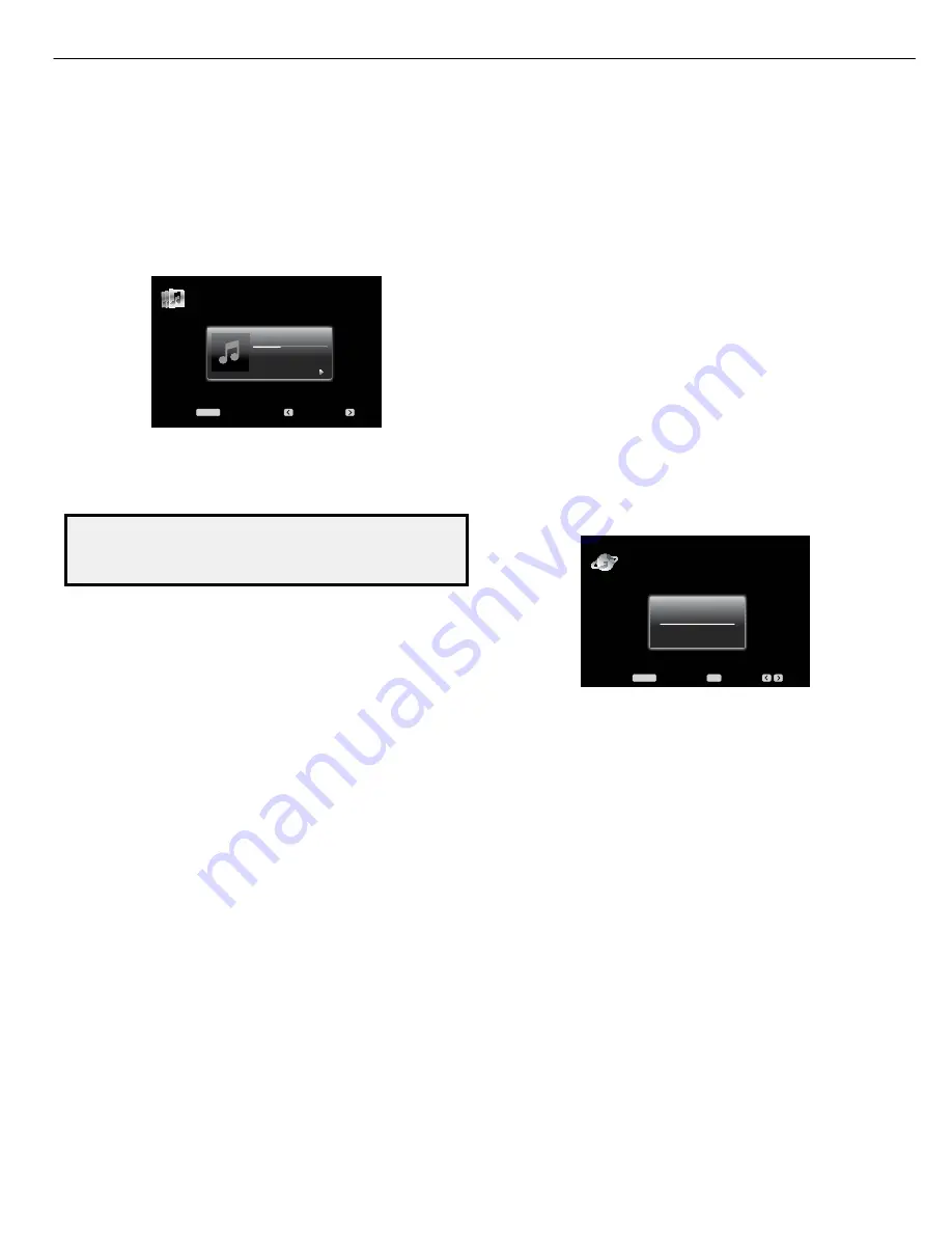
If a video monitor is connected to the AVR and the system is not in iPod manual mode, 
a The Bridge screen will appear and display the play mode icon, song title, artist and 
album. A graphic bar indicates the current play position within the track. If random or 
repeat play has been programmed, an icon will appear in the upper right corner.

The Lost Transit Center

03:41/10:44

Jugalbandi
Night Crazy

Menu:

Previous:

Next:

MENU

The Bridge

The screen may disappear from view, depending on the Setup and Slide-In Menus 
setting in the System Settings menu (described in 

System Settings

, on page 39). You 

can restore the Now Playing screen to view by pressing either of the Left or Right 
buttons.

CAUTION: We strongly recommend that you use the screen saver built 
into your video display to avoid possible damage from “burn-in” that may 
occur with plasma and many CRT displays when a still image, such as a 
menu screen, remains on the display for an extended period of time. 

Press the Menu button to view the slide-out menu:

Music:

 Select this to navigate the audio materials stored on the iPod or iPhone. Use 

the Page up/down buttons on the remote to scroll through the content a page at a 
time.

Photo/Manual:

 Select this to view still images stored on a photo-capable iPod or 

iPhone. The system will switch to iPod manual mode, and control will shift to the 
iPod. Use the screen and controls on the iPod. The AVR remote may also be used. To 
view photos on a video monitor connected to the AVR, select the photo and press the 
Play button on the iPod, or press the OK button on the remote three times.

Videos:

 Select this to view videos stored on an iPhone or an iPod that supports video 

browsing.

Notes on iPod/iPhone video playback:

• Before attempting to view photos or videos stored on your device, check the Video 
Settings menu on the device and make sure that the TV Out setting is set to On. The 
TV Signal setting should be set to match the capabilities of your video display (NTSC 
for the US; PAL for the EU). If your selection was playing and is paused, the iPod or 
iPhone requires you to reselect the video for the new TV Out setting to take effect.

• If you do not see the Videos line in the menu, and the iPod supports video browsing 
and has video content stored on it, you may need to turn off the AVR, remove the iPod 
from The Bridge IIIP, reset the iPod, turn the AVR back on and dock the iPod again. An 
iPhone may not need to be reset, as simply undocking and re-docking it may resolve 
the problem. This procedure may also help when a video program is selected but the 
Bridge screen appears instead of the video images.

To exit iPod manual mode, with the AVR remote in The Bridge mode, press the Menu 
button. To return to a previous menu level, press the Back/Exit Button or the Left 
button. 

Repeat:

 Select this setting to repeat a track or all tracks in the current album or 

playlist. Each press of the OK button switches the setting: repeat Off, repeat One or 
repeat All.

Random:

 Select this setting for random playback, also known as “Shuffle Mode.” 

Each press of the OK button switches the setting: shuffle by Song, shuffle by Album, 
or Off to end random playback.

NOTE:

 The iTunes application allows you to exempt some tracks from Shuffle mode. 

The AVR cannot override this setting.

The AVR supports audio playback from some applications available for the iPhone 
and the iPod touch. Place the system in iPod manual mode by pressing the Menu 
button and selecting “Photo/Manual.” Then use the controls on the iPhone or iPod 
touch to run the application.

Due to the wide variety of applications and many factors affecting them, playback 
is not guaranteed.

NOTES:

• The Play and Pause functions are not available unless content has been selected 
for playback.

• To search within a track, press and hold the forward or reverse Transport Control 
button. Press the previous track Transport Control button once to skip to the beginning 
of the current track; press the previous track Transport Control button twice to skip to 
the beginning of the previous track.

Listening to Internet Radio

Your AVR’s Network connection brings you a world of MP3- and WMA-format streams 
via the Internet. After you have successfully connected to your home network as 
described in 

Connect to Your Home Network

, on page 20, and set up the network 

as described in 

Set Up the Network

, on page 27, press the Network Source Selector 

button on the remote. Each press toggles between the Network and Internet Radio 
screens.

Internet Radio

Big Blue Swing

Count Basie

Menu:

Set Presets:

Presets:

OK

MENU

With the Internet Radio screen (above) displayed, the AVR will automatically connect 
to the Internet via the www.radioharmankardon.com portal. To select a stream, press 
the Menu button, and use the Up/Down buttons to search by category: Presets, My 
Favourites, Local Stations, HDi, Stations, Podcasts or My Added Stations. 

NOTE:

 The 

categories displayed may vary by region.

To create a Favourites list, log onto www.radioharmankardon.com from your 
computer. Enter your AVR’s ID # (to see the ID # with the Internet Radio screen 
displayed, press the Menu button, then select Help) and create an account. Favourites 
that you select on the Web site will be available on the AVR.

NOTE:

 While the Help screen is displayed, we recommend spending a few moments 

listening to the audio FAQs to get answers to common questions about Internet radio 
operation. The FAQs play in a continuous loop. To return to an Internet radio station 
while an FAQ is playing, press the Menu button, then the Back/Exit button, then the 
Back/Exit button again, and select an Internet radio station.

Navigation is similar to other slide-in menus. Scroll to the desired item and press the 
OK button or the Right button to select it. To return to the previous menu level (or to 
clear the top-level menu from view), press the Back/Exit button or the Left button.

If you know the URL (Web address) of a specific audio stream, select the Direct 
Station option from the menu. A live stream is required. The AVR is not able to 
connect to streams that require site registration or other interaction prior to playing 
the stream. If the AVR cannot connect to the stream, a “Station Not Live” message 
will appear briefly, and the Internet Radio screen will remain essentially blank. Not 
all URLs will be accessible.

Internet Radio Presets

You can program up to 30 Internet radio stations as presets. To set a preset, first tune 
the station. Press the OK button, and two dashes will flash. Enter the preset number 
(any number from 1 through 30) using the Number buttons. The connection to the 
station will momentarily stop, interrupting the program, and the AVR will reconnect 
to the station.

To connect to a station programmed as a preset, enter its preset number using the 
Number buttons, or use the Left/Right buttons to select it from the preset list.

AVR 2650   


harman/kardon


22

Summary of Contents for AVR 2650

Page 1: ... FUNCTIONS 10 CONNECTIONS INSTALLATION 12 OPERATION 19 TROUBLESHOOTING GUIDE 24 REMOTE PROCESSOR RESETS 25 DISASSEMBLY 26 UNIT EXPLODED VIEW 27 EXPLODED VIEW PARTS LIST 28 AMP BIAS ADJUSTMENT 29 BLOCK DIAGRAM 30 PCB DRAWINGS 32 ELECTRICAL PARTS LIST 47 SEMICONDUCTOR PINOUTS 103 SCHEMATICS 224 WIRING DIAGRAM 241 harman kardon Inc Released 2011 8500 Balboa Blvd Discontinued XXXX Northridge CA 91329 ...

Page 2: ...or to applying power to the unit under test 2 After removing an electrical assembly equipped with ES devices place the assembly on a conductive surface such as aluminum foil to prevent electrostatic charge build up or exposure of the assembly 3 Use only a grounded tip soldering iron to solder or unsolder ES devices 4 Use only an anti static solder removal device Some solder removal devices not cla...

Page 3: ...l overlays control shaft etc Plug the AC line cord of the appliance directly into a 120V AC 60Hz outlet and turn the AC power switch on Any current measured must not exceed o 5mA ANY MEASUREMENTS NOT WITHIN THE LIMITS OUTLINED ABOVE ARE INDICATIVE OF A POTENTIAL SHOCK HAZARD AND MUST BE CORRECTED BEFORE RETURNING THE APPLIANCE TO THE CUSTOMER Device under test Test all exposed metal surfaces Also ...

Page 4: ...tereo 70dB 68dB Distortion mono stereo 0 2 0 3 Stereo separation 40dB 1kHz Selectivity 400kHz 70dB Image rejection 80dB IF rejection 90dB AM Tuner Section Frequency range 520 1710kHz AVR 3650 AVR 2650 522 1620kHz AVR 365 AVR 265 Signal to noise ratio 45dB Usable sensitivity loop 500μV Distortion 1kHz 50 mod 0 8 Selectivity 10kHz 30dB Video Section Television format NTSC AVR 3650 AVR 2650 PAL AVR 3...

Page 5: ...FOAM PAD L FOAM PAD R AVR 2650 OUTER CARTON AVR 2650 OUTER CARTON AVR 2650 harman kardon 5 ...

Page 6: ...utton Source List Button Surround Modes Button Left Right Buttons Headphone Jack EzSet EQ Mic Input Continued on next page Power Indicator Message Display Volume Knob Video Modes Button Setup Button IR Sensor Power Button Left Right Buttons Headphone Jack EzSet EQ Mic Input Back Exit Button Resolution Button Audio Effects Button Surround Modes Button Up Down Buttons USB Port OK Button HDMI Front I...

Page 7: ...ct an HDMI capable source component that will be used only temporarily such as a camcorder or game console here Resolution button Press this button to access the AVR s video output resolution setting 480i 480p 720p 1080i 1080p or 1080p 24Hz Use the Up Down and OK buttons to change the setting IMPORTANT NOTE If you set the AVR s video output resolution higher than the capabilities of the actual con...

Page 8: ...s You will also need to make an audio connection from the source device to the AVR See Connect Your Audio and Video Source Devices on page 18 for more information Digital Audio Input connectors If your non HDMI source devices have digital outputs connect them to the AVR s digital audio connectors NOTE Make only one type of digital connection HDMI optical or coaxial from each device See Connect You...

Page 9: ...er with a line level input See Connect Your Subwoofer on page 17 for more information Analog Audio Input connectors Use the AVR s Analog Audio Input connectors for source devices that don t have HDMI or digital audio connectors See Connect Your Audio and Video Source Devices on page 18 for more information Optical Digital Output connector Connect a digital audio recorder s optical digital input to...

Page 10: ...h Source Selector Buttons AVR 2650 AVR 265 AVR Power On Off Buttons Audio Effects Button Back Exit Button A B C D Buttons Volume Up Down Buttons Mute Button Info Button AVR Button Zone Selector Switch OK Button Last Channel Button Video Modes Button IR Transmitter Lens Device Power On Off Buttons Surround Modes Button Number Buttons Activity Button Menu Button Disc Menu Button Sleep Button Learn B...

Page 11: ...nu in the hierarchy See the Advanced Functions section on page 33 for more information Number buttons Use these buttons to enter numbers for radio station frequencies or to select station presets Last Channel button When controlling a cable satellite or HDTV set top box or a TV press this button to return to the previous television channel Activity button With this button you can program the remot...

Page 12: ...t looks similar to a full range analog audio jack it is filtered so that only the low frequencies pass through it Don t connect this output to any device other than a subwoofer Source Device Connections Audio and video signals originate in source devices components where a playback signal originates such as your Blu ray Disc or DVD player CD player DVR digital video recorder or other recorder tape ...

Page 13: ...IP outputs analog audio to the AVR and is available as a source to Zone 2 in a multizone system Video Connections Many source devices output both audio and video signals e g Blu ray Disc DVD player cable television box HDTV tuner satellite box VCR DVR In addition to an audio connection as described above make a video connection for each of these source devices Make only one type of video connectio...

Page 14: ...or content from other DLNA compatible devices that are connected to the same network Use a Cat 5 or Cat 5E cable to connect the AVR s RJ 45 connector to your home network USB Port The USB port on your AVR is used for firmware upgrades If an upgrade for the AVR s operating system is released in the future you will be able to download it to the AVR using this port Complete instructions will be provid...

Page 15: ...ut making connections to it AVR Subwoofer Connector Powered Subwoofer Single RCA Audio Cable not supplied Single RCA Audio Cable not supplied Powered Subwoofer AVR Subwoofer Connector Connect Your TV or Video Display If your TV has an HDMI connector Use an HDMI cable not included to connect it to the AVR s HDMI Monitor Out connector You do not need to make any other connections to your TV from the...

Page 16: ...ble not supplied To Composite Video Output Receiver Video Connectors Composite Video Equipped Source Device Composite Video Cable not supplied To Composite Video Output Connect Your Optical Digital Video Devices If your non HDMI source devices have optical digital outputs connect them to the AVR s optical digital audio connectors NOTE Make only one type of digital connection HDMI optical or coaxia...

Page 17: ...he Bridge IIIP connector Insert the plug until it snaps into place in the connector IMPORTANT Connect The Bridge IIIP only with the AVR s power turned OFF The Bridge IIIP AVR The Bridge IIIP Connector The Bridge IIIP Dock your iPod or iPhone not included in The Bridge IIIP and you may listen to its audio through your high performance audio video system You may also view still images or video mater...

Page 18: ...AVR will supply power to the SIRIUS module so you will not need to connect the power supply included with the module You will need to purchase a SIRIUS radio subscription and activate the tuner module following the instructions included with the SIRIUS module and from the SIRIUS Web site at www sirius com AVR SIRIUS Tuner Connector Eight Pin DIN Cable supplied with SIRIUS tuner SIRIUSConnect Tuner...

Page 19: ...rocessing desired Setting Effect Off No Dolby Volume processing Low Only Dolby Volume Modeler module is active Medium Both Modeler and Leveler modules are active Leveler module has a value of 3 Max Both Modeler and Leveler modules are active Leveler module has a value of 9 NOTE Dolby Volume processing is compatible with sources recorded at a sampling rate of 48kHz High resolution sources such as D...

Page 20: ...om your most trusted sources SIRIUS Satellite Radio is available to residents of the U S except Alaska and Hawaii and Canada To listen to SIRIUS Satellite Radio you ll need to connect a SIRIUS tuner module sold separately to the AVR s SIRIUS Tuner connector SIRIUS tuner modules that will work with your AVR are available at www sirius com Select a tuner module designated for SIRIUS Ready audio comp...

Page 21: ...nd select the Random Music setting Each press of the OK button turns the setting on or off The AVR will automatically repeat the tracks until playback is stopped manually To collapse a folder or return to the previous menu level press the Back Exit button or the Left button Listening to an iPod iPhone Device When The Bridge IIIP is connected to its proprietary input on the AVR and an iPod or iPhon...

Page 22: ... applications available for the iPhone and the iPod touch Place the system in iPod manual mode by pressing the Menu button and selecting Photo Manual Then use the controls on the iPhone or iPod touch to run the application Due to the wide variety of applications and many factors affecting them playback is not guaranteed NOTES The Play and Pause functions are not available unless content has been s...

Page 23: ...n front panel or remote The Surround Modes menu will appear Surround Modes Cable Sat Auto Select AVR Selects Best Mode Virtual Surround For Two Speaker Systems Stereo Movie Music Video Game 2 CH Stereo Logic 7 Movie Logic 7 Music Logic 7 Game Press the Up Down buttons repeatedly until the desired surround mode category appears Auto Select Virtual Surround Stereo Movie Music or Video Game Press the...

Page 24: ...Move the AVR or antenna away from computers fluorescent lights motors or other electrical appliances AVR 3650 AVR 365 only Surround back speaker settings cannot be accessed and the test tone does not play through the surround back speakers Multi zone operation has been selected Assigned AMP channels have been assigned to Zone 2 Use the Speaker Setup menu to reassign the Assigned AMP to the surroun...

Page 25: ...s described below NOTE A processor reset erases all user configurations including video resolution speaker and level settings and tuner presets After a reset reenter all of these settings from your notes in the Appendix worksheets To reset the AVR s processor 1 Press the front panel Standby On switch to place the unit in the Standby mode the Power Indicator LED will turn amber 2 Press and hold the...

Page 26: ...AVR 2650 harman kardon 26 ...

Page 27: ... SCREW SPECIAL 2 S8 CTS3 8JFZR SCREW 4 S12 SCREW CHD3A012R 5 S17 S17 SCREW CTB3 8JR 7 VIDEO PCB POWER LED PCB VOLUME PCB 43 3 S1 29 S5 S3 S3 17 S1 S5 S1 50 34 18 18 35 41 2 44 45 46 1 46 2 48 BRACKET PCB HEAT SINK FOOT A FOOT B CHASSIS BOTTOM CABINET TOP CMY4A314 CUA4A294 CKL1A095 CKC6B145S60 CMD1A417 CKL1A094 1 2 2 2 1 1 CUSHION FOOT CHG1A373 4 BRACKET FAN CMD1A694 1 RUBBER CHG1A309 1 CLAMPER WIR...

Page 28: ...AVR 2650 harman kardon 28 ...

Page 29: ...1 CEN CN64 SR CN63 FL CN65 SBLPSju YOmyPSju OziyP NO 1 2 3 Surround Left Surround Right 4 5 Channel Front Left Front Right Center Adjust for Adjustment 25 92mV 5 CN65 CN64 25 92mV 5 25 92mV 5 25 92mV 5 25 92mV 5 CN63 CN62 CN61 CN66 CN67 6 Surround Back Left 25 92mV 5 25 92mV 5 Surround Back Right 7 CN66 CN61 CN64 CN63 CN65 CN67 CN62 DC EVM 03 PCB VR8 VR8 VR8 VR8 VR8 VR8 VR8 AVR 2650 harman kardon ...

Page 30: ...30 ...

Page 31: ...31 ...

Page 32: ...32 ...

Page 33: ...33 ...

Page 34: ...34 ...

Page 35: ...35 ...

Page 36: ...36 ...

Page 37: ...37 ...

Page 38: ...38 ...

Page 39: ...39 ...

Page 40: ...40 ...

Page 41: ...41 ...

Page 42: ...42 ...

Page 43: ...43 ...

Page 44: ...44 ...

Page 45: ...45 ...

Page 46: ...46 ...

Page 47: ...H101T CAP ELECT 10V 100uF KR3 10V101MA 5 11L C557 CCBS1H103ZFT CAP CERAMIC 0 01UF 50V Z C558 CCBS1H103ZFT CAP CERAMIC 0 01UF 50V Z C631 CCBS1H104ZFT CAP CERAMIC 0 1UF 50V Z C651 CCBS1H104ZFT CAP CERAMIC 0 1UF 50V Z C652 CCBS1H471KBT CAP CERAMIC 470PF 50V CH UP025 B471K A B Z C653 CCBS1H471KBT CAP CERAMIC 470PF 50V CH UP025 B471K A B Z C714 CCBS1H223ZFT CAP CERAMIC 22000PF 50V CH UP025 F223Z A B J ...

Page 48: ...Q906 HVTKRA107MT TRANSISTOR TO 92M KRA107M Q907 HVTKRA107MT TRANSISTOR TO 92M KRA107M Q941 HVTKTC2874BT TRANSISTOR MUTE KTC2874B Q942 HVTKTC2874BT TRANSISTOR MUTE KTC2874B Q943 HVTKTC2874BT TRANSISTOR MUTE KTC2874B Q944 HVTKTC2874BT TRANSISTOR MUTE KTC2874B Q951 HVTKRC107MT TRANSISTOR TO 92M KRC107M Q952 HVTKRA107MT TRANSISTOR TO 92M KRA107M Q954 HVTKRC107MT TRANSISTOR TO 92M KRC107M R101 CRD20TF2...

Page 49: ...ohm J R722 CRD20TJ101T RES CARBON 1 5W 100ohm J R731 CRD20TJ100T RES CARBON 1 5W 10ohm J R735 CRD20TJ152T RES CARBON 1 5W 1 5Kohm J R741 CRD20TJ123T RES CARBON 1 5W 12Kohm J R742 CRD20TJ102T RES CARBON 1 5W 1Kohm J R801 CRD20TJ101T RES CARBON 1 5W 100ohm J R802 CRD20TJ101T RES CARBON 1 5W 100ohm J R811 CRD20TJ104T RES CARBON 1 5W 100Kohm J R812 CRD20TJ102T RES CARBON 1 5W 1Kohm J R813 CRD20TJ103T ...

Page 50: ...N61 CJP06GB142ZB PIN HEADER 6P 2 54mm BN73 CJP06GB142ZB PIN HEADER 6P 2 54mm BN74 CWB1C005100BM WIRE ASS Y 5P 100MM CN61 CJP06GA221ZB FEMALE HEADER 6P 2 54mm STRAIGHT TYPE FAS2851 CN71 CJP05GB03ZY WAFER YMAW025 2 5mm ANGLE CN72 CJP27GA285ZN WAFER FPC 1 25mm stright 1 25 2 NP CN73 CJP06GB143ZB FEMALE HEADER 6P 2 54mm CN74 CJP05GB03ZY WAFER YMAW025 2 5mm ANGLE C411 CCEA1JH101E CAP ELECT 100UF 63V D1...

Page 51: ... CMD1A702 FRAME BOTTOM CMD1A786 BRACKET HDMI CNVFS2026 020021 MODULE VENICE6 2 NO DAB NO WIFI INPUT PCB ASS Y COP12327D C133 CCUS1H104KC CAP CHIP 1608 50V 0 1uF C134 CCUS1H104KC CAP CHIP 1608 50V 0 1uF C135 CCUS1H104KC CAP CHIP 1608 50V 0 1uF C136 CCUS1H104KC CAP CHIP 1608 50V 0 1uF C217 CCUS1H101JA CAP CHIP 1608 50V 100pF C218 CCUS1H101JA CAP CHIP 1608 50V 100pF C219 CCUS1H101JA CAP CHIP 1608 50V...

Page 52: ...IP 1608 50V 0 1uF C605 CCUS1H104KC CAP CHIP 1608 50V 0 1uF C607 CCUS1H104KC CAP CHIP 1608 50V 0 1uF C609 CCUS1H104KC CAP CHIP 1608 50V 0 1uF C611 CCUS1H104KC CAP CHIP 1608 50V 0 1uF C613 CCUS1H104KC CAP CHIP 1608 50V 0 1uF C615 CCUS1H104KC CAP CHIP 1608 50V 0 1uF C617 CCUS1H104KC CAP CHIP 1608 50V 0 1uF C619 CCUS1H104KC CAP CHIP 1608 50V 0 1uF C621 CCUS1H104KC CAP CHIP 1608 50V 0 1uF C623 CCUS1H10...

Page 53: ...CHIP 1608 50V 0 1uF C761 CCUS1H104KC CAP CHIP 1608 50V 0 1uF C762 CCUS1H104KC CAP CHIP 1608 50V 0 1uF C763 CCUS1H104KC CAP CHIP 1608 50V 0 1uF C765 CCUS1H104KC CAP CHIP 1608 50V 0 1uF C773 CCUS1H104KC CAP CHIP 1608 50V 0 1uF C780 CCUS1H102KC CAP CHIP 1608 50V 1000pF C781 CCUS1H223KC CAP CHIP 1608 50V 0 022uF C788 CCUS1H104KC CAP CHIP 1608 50V 0 1uF C789 CCUS1H103KC CAP CHIP 1608 50V 0 01uF C792 CC...

Page 54: ...04T RES CHIP 1608 5 100Kohm R400 CRJ10DJ104T RES CHIP 1608 5 100Kohm R401 CRJ10DJ104T RES CHIP 1608 5 100Kohm R402 CRJ10DJ104T RES CHIP 1608 5 100Kohm R403 CRJ10DJ104T RES CHIP 1608 5 100Kohm R404 CRJ10DJ182T RES CHIP 1608 5 1 8Kohm R406 CRJ10DJ101T RES CHIP 1608 5 100ohm R407 CRJ10DJ101T RES CHIP 1608 5 100ohm R424 CRJ10DJ472T RES CHIP 1608 5 4 7Kohm R425 CRJ10DJ392T RES CHIP 1608 5 3 9Kohm R448 ...

Page 55: ...10Kohm R908 CRJ10DJ105T RES CHIP 1608 5 1Mohm R910 CRJ10DJ105T RES CHIP 1608 5 1Mohm R925 CRJ10DJ0R0T RES CHIP 1608 5 0ohm R932 CRJ10DJ103T RES CHIP 1608 5 10Kohm R963 CRJ10DJ105T RES CHIP 1608 5 1Mohm R966 CRJ10DJ472T RES CHIP 1608 5 4 7Kohm R968 CRJ10DJ105T RES CHIP 1608 5 1Mohm R969 CRJ10DJ103T RES CHIP 1608 5 10Kohm C111 CCUI1C104KC CAP CHIP 1005 16V 0 1uF C112 CCUI1C104KC CAP CHIP 1005 16V 0 ...

Page 56: ... 1608 50V 390pF C325 CCUS1H391JA CAP CHIP 1608 50V 390pF C326 CCUS1H822KC CAP CHIP 1608 50V 8200pF C327 CCUS1H391JA CAP CHIP 1608 50V 390pF C328 CCUS1H391JA CAP CHIP 1608 50V 390pF C329 CCUS1H391JA CAP CHIP 1608 50V 390pF C330 CCUS1H391JA CAP CHIP 1608 50V 390pF C331 CCUS1H391JA CAP CHIP 1608 50V 390pF C358 CCUS1H392KC CAP CHIP 1608 50V 3900pF C359 CCUS1H822KC CAP CHIP 1608 50V 8200pF C363 CCUI1E1...

Page 57: ...0V 0 01uF C791 CCUS1H104KC CAP CHIP 1608 50V 0 1uF C794 CCUI1H181JA CAP CHIP 1005 50V 180pF C795 CCUI1H181JA CAP CHIP 1005 50V 180pF C797 CCUI1C104KC CAP CHIP 1005 16V 0 1uF C798 CCUI1C104KC CAP CHIP 1005 16V 0 1uF C801 CCUS1H180JA CAP CHIP 1608 50V 18pF C802 CCUS1H180JA CAP CHIP 1608 50V 18pF C820 CCUS1H104KC CAP CHIP 1608 50V 0 1uF C830 CCUS1H104KC CAP CHIP 1608 50V 0 1uF C831 CCUS1H104KC CAP CH...

Page 58: ...SE AZ4580MTR E1 SOIC8 BCD IC140 CVITC74HC151AFN I C 8 CHAN MULTIPLEXER SOL16 P 150 1 27 TC74HC151AFN IC141 CVICS497024CVZ I C DSP CIRRUS LOGIC CS497024CVZ IC142 CVICS49DV8CCVZ I C DSP DOLBY VOLUME CIRRUS LOGIC CS49DV8CCVZ IC143 HVICS42528 CQ I C CODEC DIR CIRRUS LOGIC CS42528 CQ IC144 CVIM12L16161A5TG I C 16MB SDRAM ESMT M12L16161A5TG IC145 HVITC74VHC157FT I C 2 CHANNEL MUX TOSHIBA TC74VHC157FT IC...

Page 59: ... B RTK Q306 HVTKTC812TB TRANSISTOR CHIP TS6 KTC812T B RTK Q307 HVTKRA107S TRANSISTOR CHIP SOT 23 KRA107S Q308 HVTKRA107S TRANSISTOR CHIP SOT 23 KRA107S Q402 HVTKTC812TB TRANSISTOR CHIP TS6 KTC812T B RTK Q729 HVTKRC107S TRANSISTOR CHIP SOT 23 KRC107S Q730 HVTKRC107S TRANSISTOR CHIP SOT 23 KRC107S Q732 HVTKRC107S TRANSISTOR CHIP SOT 23 KRC107S Q734 HVTKRC107S TRANSISTOR CHIP SOT 23 KRC107S Q738 CVTK...

Page 60: ...0DJ104T RES CHIP 1608 5 100Kohm R151 CRJ10DJ104T RES CHIP 1608 5 100Kohm R152 CRJ10DJ104T RES CHIP 1608 5 100Kohm R156 CRJ10DJ101T RES CHIP 1608 5 100ohm R158 CRJ06IJ330T RES CHIP 1005 5 33ohm R161 CRJ10DJ104T RES CHIP 1608 5 100Kohm R162 CRJ10DJ102T RES CHIP 1608 5 1Kohm R166 CRJ10DJ0R0T RES CHIP 1608 5 0ohm R167 CRJ10DJ0R0T RES CHIP 1608 5 0ohm R172 CRJ10DJ103T RES CHIP 1608 5 10Kohm R173 CRJ10D...

Reviews: