


OPERATION
37
ENGLISH
Operation
Tape Recording
In normal operation, the audio or video source
selected for listening through the AVR is sent to
the record outputs. This means that any program
you are watching or listening to may be recorded
simply by placing machines connected to the
outputs for
Tape Outputs
3
or
Video 1
Outputs
P7
in the record mode.
When a digital audio recorder is connected to
any of the
Digital Audio Outputs
A
, you are
able to record the digital signal using a CD-R,
MiniDisc or other digital recording system.
Note that all digital signals will be passed
through to both, coaxial and optical, digital
outputs simultanously, no matter which kind of
digital input was selected.
NOTES:
• The digital outputs are active only when a digital
signal is present, and they do not convert an analog
input to a digital signal, or change the format of the
digital signal (e.g. Dolby Digital to PCM or vice
versa, but coaxial digital signals are converted to
optical signals and vice versa). In additon, the digi-
tal recorder must be compatible with the output
signal. For example, the PCM digital output from a
CD player may be recorded on a CD-R or MiniDisc,
but Dolby Digital or DTS signals may not.
• To make an analog recording from a digital source
is possible, but only from a PCM source (not Dolby
Digital or DTS) and correctly only with "Surround
Off" mode (with any Surround mode only the L/R
front signals will be fed to the record outputs).
Output Level Adjustment
With Source Signals
Normal output level adjustment for the AVR is
established using the test tone, as outlined on
page 27-28. In some cases, however, it may be
desirable to adjust the output levels using
program material such as a test disc, or a selection
you are familiar with. Additionally, the output level
for the subwoofer and those for the Stereo modes
can only be adjusted using this procedure.
To adjust the output levels using program
material, first select the surround mode for which
you want to trim the speakers (see NOTE below),
start your program material source and set the
reference volume for the front left and front right
channels using the
Volume Control
.
Once the reference level has been set, press the
Channel Select
button
C
Ù
and note that
FRONT L LEVEL
will appear in the
Main
Information Display
Ò
. To change the level, first
press the
OK
button
F
@
, and then use the
Selector
buttons
7
or the
⁄
/
¤
buttons
D
to
raise or lower the level. DO NOT use the volume
control, as this will alter the reference setting.
Once the change has been made, press the
OK
button
F
@
and then press the
Selector
but-
tons
7
or the
⁄
/
¤
buttons
D
to select the
next output channel location that you wish to
adjust. To adjust the subwoofer level, press the
Selector
buttons
7
or the
⁄
/
¤
buttons
D
until
WOOFER LEVEL
appears in the
Main
Information Display
Ò
or on-screen display
(only available if the subwoofer is turned on).
Press the
OK
button
F
@
when the name of
the desired channel appears in the
Main
Information Display
Ò
and on-screen dis-
play, and follow the instructions shown above to
adjust the level.
Repeat the procedure as needed until all chan-
nels requiring adjustment have been set. When
all adjustments have been made and no further
adjustments are made for five seconds, the AVR
will return to normal operation.
The channel output may also be adjusted using
the full-OSD on-screen menu system. First, set
the volume to a comfortable listening level using
the
Volume Control
1
. Then, press the
OSD button
L
to bring up the
MASTER
MENU
(Figure 1). Press the
¤
Button
D
three
times until the on-screen
›
cursor is next to the
MANUAL ADJUST
line. Press the
OK
Button
F
to activate the
MANUAL ADJUST
and
use the
⁄
/
¤
D
to scroll to the
CHANNEL
ADJUST
line. Press the
OK
Button
F
to dis-
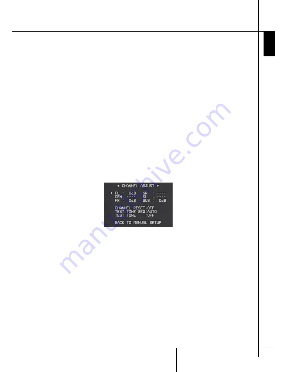
play the
CHANNEL ADJUST
submenu.
Figure 11
When the menu appears, the internal test tone
will be turned off. This will allow you to use your
external test disc or other source material as the
test signal. Then, use the
⁄
/
¤
Buttons
D
to
select the channels to be adjusted. At each
channel position use the
‹
/
›
Buttons
E
to change the output level.
Remember, when you are using a disc with test
signal (e.g. pink noise) or an external signal
generator as the source, the goal is to have the
output level at each channel be equal when
heard at the listening position, with any surround
mode selected. When your test source is a nor-
mal disc with music signals, you may adjust the
level for each channel and surround mode as you
prefer, e.g. you may lower the center channel
level when you find it to be too high or increase
the level of the rears when you find it to be too
low with specific surround modes.
If you wish to reset all the levels to their original
factory default of 0dB offset, press the
⁄
/
¤
Buttons
D
so that the on-screen cursor is next
to the
CHANNEL RESET
line and press the
‹
/
›
Buttons
E
so that the word
ON
is
highlighted. After the levels are reset, resume the
procedure outlined above to reset the levels to
the desired settings. When all adjustments are
done, press the
⁄
/
¤
Buttons
D
to move the
on-screen
fi
cursor so that it is next to
BACK
TO MASTER MENU
and then press the
OK
Button
F
if you wish to go back to the main
menu to make other adjustments. If you have no
other adjustments to make, press the
OSD
Button
L
to exit the menu system.
NOTE:
The output levels may be separately trimmed
for each digital and analog surround mode. If you
wish to have different trim levels for a specific
mode, select that mode and then follow the instruc-
tions in the steps shown above.
With Stereo modes the adjustment procedure
described above is the only way to trim the output
level, e.g. to match the Stereo level with other
modes.


