POWER CASE INSPECTION
1. Check all electrical connections in the power case to be sure they are secure.
2. Check the spindle overload setting:
A) Verify the spindle overload is properly set for the machine voltage. The table shown below
reflects the data shown on the spindle Full Load Amp tag, located on the front of the machine
head.
50 Hz Electrical Service
60 Hz Electrical Service
Voltage
Full Load Amps
Voltage
Full Load Amps
200 V
6.5
200 V
6.2
220 V
6.6
208 V
6.1
380 V
3.3
220 V
5.8
415 V
3.2
230 V
5.8
440 V
3.3
460 V
2.9
B) Locate the appropriate Full Load Amp value for the machine, based on the frequency and
voltage of the electrical service to be used.
C) Multiply the Full Load Amp value by "1.1". The result will be a realistic setting for the spindle
overload.
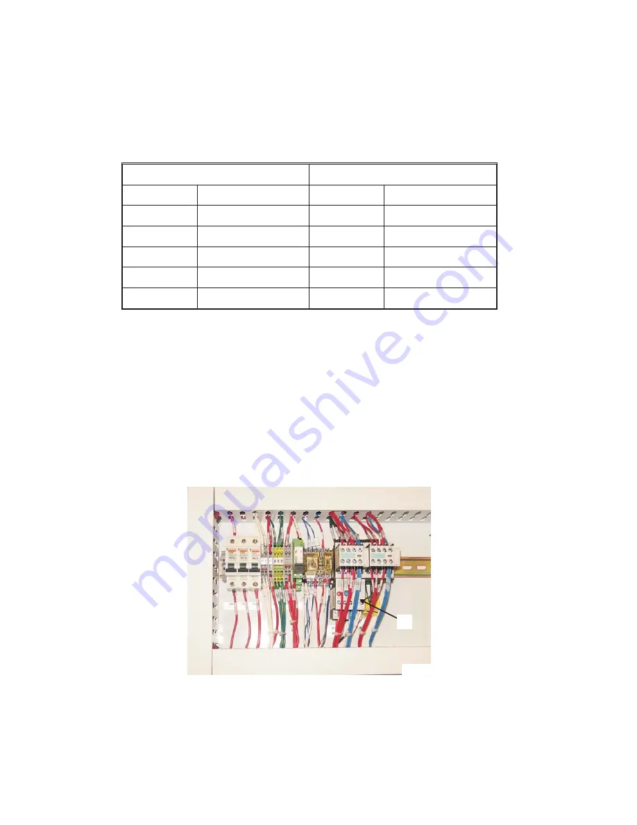
D) Check the adjustable dial on spindle overload "M", Figure 2.12, to be sure the setting
matches the value calculated in the previous step. Adjust if necessary.
2-8
M-477A
Figure 2.12 - Spindle Overload Relay
and Ground Connection
M
TP6988
Summary of Contents for Bridgeport EZ Vision
Page 10: ... NOTES viii M 477A ...
Page 18: ...HEAD DIMENSIONS 1 8 M 477A Figure 1 5 Head Dimensions TP5663 ...
Page 20: ... NOTES 1 10 M 477A ...
Page 36: ... NOTES 2 16 M 477A ...
Page 44: ... NOTES 3 8 M 477A ...
Page 58: ... NOTES 4 14 M 477A ...
Page 64: ... NOTES 5 6 M 477A ...
Page 70: ... NOTES 6 6 M 477A ...
Page 71: ...CHAPTER 7 PARTS LISTINGS HEAD TOP HOUSING M 477A 7 1 TP5340 ...
Page 74: ...HEAD BACK GEAR 7 4 M 477A TP5341 ...
Page 78: ...HEAD LOWER HOUSING 7 8 M 477A TP5343 ...
Page 84: ...BASIC MACHINE 7 14 M 477A TP5344 ...
Page 96: ...OPERATOR PENDANT DC150 Motion Control System 7 26 M 477A TI5563 ...
Page 97: ...POWER CASE EXTERNAL VIEW DC150 Motion Control System M 477A 7 27 TI5564 ...
Page 103: ... NOTES M 477A 7 33 ...
Page 104: ......


