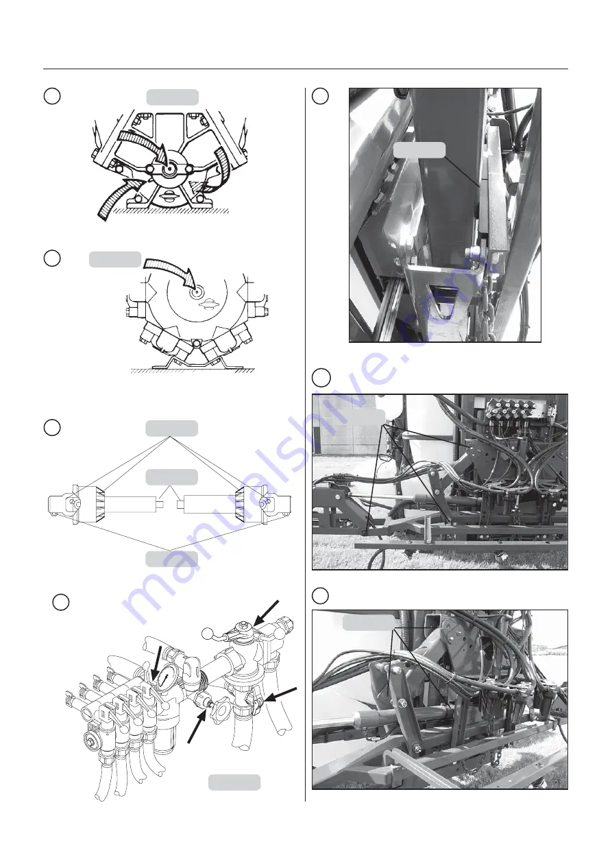
Hardi MASTER HVZ Series Instruction Book Download Page 31

31

GB 13 00 MA

Maintenance

T212-0023

A - 10h

A - 10h

A - 10h

A - 10h

A - 10h

B - 50h

B - 50h

B - 50h

B - 50h

B - 50h

C - 50h

C - 50h

C - 50h

C - 50h

C - 50h

T226-0001

2

1

A - 50h

A - 50h

A - 50h

A - 50h

A - 50h

1

A - 50h

A - 50h

A - 50h

A - 50h

A - 50h

C - 20h

C - 20h

C - 20h

C - 20h

C - 20h

3

Models with BK control unit only

4

D - 50h

D - 50h

D - 50h

D - 50h

D - 50h

T212-0029

5

B - 50h

B - 50h

B - 50h

B - 50h

B - 50h

5

T212-0024

C - 50h

C - 50h

C - 50h

C - 50h

C - 50h

Summary of Contents for MASTER HVZ Series

Page 1: ...al information and data in this book are to the best of our belief correct at the time of printing As it is HARDI INTERNATIONAL A S policy permanently to improve our products we reserve the right to make changes in design features accessories specifications and maintenance instructions at any time and without notice HARDI INTERNATIONAL A S is without any obligation in relation to implements purcha...

Page 2: ...2 ...

Page 3: ...wer supply 13 Basic adjustment of the boom 14 Operation Operating the boom 16 Operation liquid system 18 Maintenance General guidelines 28 Lubrication 30 10 hours service 33 50 hours service 34 250 hours service 34 1000 hours service 34 Occasional maintenance 35 Off season storage 40 Fault finding 41 Technical specifications 44 Subject index 47 Table of Contents ...

Page 4: ... June 1989 on mutual approximation of the laws of the Member States on the safety of machines 89 392 EEC as amended by directives 91 368 EEC and 93 368 EEC with special reference to Annex 1 of the Directive on essential safety and health requirements in relation to the construction and manufacture of machines B was manufactured in conformity with the current standards implementing harmonised stand...

Page 5: ...advice Remember to identify chemicals used Keep children away from the equipment Do not attempt to enter the tank Do not go under any part of the sprayer unless it is secured The boom is secure when placed in the transport brackets If any portion of this instruction book remainsun clear after reading it contact your HARDI dealer for further explanation before using the equip ment Saf Saf Saf Saf S...

Page 6: ... pump model 1302 or 363 The design of the diaphragm pump is simple with easily accessible diaphragms and valves which ensures liquid does not contact the vital parts of the pump MANIFOLD sy MANIFOLD sy MANIFOLD sy MANIFOLD sy MANIFOLD system stem stem stem stem The functions of the spray circuits are operated via the centrally situated MANIFOLD valves with colour coded plates and pictorial symbols...

Page 7: ... 5 15 16 and 18 m working width Alternative boom widths are possible for the VHZ model All booms are provided with spring loaded breakaway Identif Identif Identif Identif Identifica ica ica ica ication pla tion pla tion pla tion pla tion plates tes tes tes tes An identification plate fitted on the frame indicates producer name model own weight max height max pressure of the hydraulic system and ma...

Page 8: ... oper opera a a a ation tion tion tion tion Although the sprayer has been applied with a strong and protective surface treatment on steel parts bolts etc in the factories it is recommended to apply a film of anticorrosion oil e g CASTROL RUSTILLO or SHELL ENSIS FLUID on all metal parts in order to avoid chemicals and fertilisers discoloring the enamel If this is done before the sprayer is put into...

Page 9: ...nt suspension cat II A quick hitch A is supplied with the sprayer Fit the quick hitch to the tractor for easy hook up of the sprayer Frontvægt Suppor Suppor Suppor Suppor Support le t le t le t le t legs gs gs gs gs The frame has two retractable support legs that can be turned in to minimise crop damage NOTE The support legs must be unfolded before lowering and disconnecting the sprayer How to unf...

Page 10: ...nd equip implements accordingly R R R R Rear lights optional equipment ear lights optional equipment ear lights optional equipment ear lights optional equipment ear lights optional equipment The sprayer can be equipped with rear lights A Connect plug for rear lights to the tractor s 7 pin socket and check the functions of rear lights stop lights and direction indicators on both sides of the spraye...

Page 11: ...d remove the ignition key before carrying out maintenance or repairs to the transmission shaft or implement Installa Installa Installa Installa Installation of tion of tion of tion of tion of tr tr tr tr transmission shaft ansmission shaft ansmission shaft ansmission shaft ansmission shaft First installation of the transmission shaft is done in the following way 1 Attach sprayer to tractor and set...

Page 12: ...03 01 Sprayer setup 7 Fit the chains to prevent the protection guards from rotating with the shaft 8 To ensure long life of the transmission shaft try to avoid working angles greater than 15 T259 0008 T259 0009 ...

Page 13: ... bar and an oil capacity of approx 2 litres After having operated the boom and the system has been filled with oil check tractor s hydraulic oil level and top up if necessary Saf Saf Saf Saf Safety inf ety inf ety inf ety inf ety informa orma orma orma ormation tion tion tion tion WARNING Test of the hydraulic system should be done very cautiously There may be air trapped in the system which can c...

Page 14: ...tion te section Before commencing this job make sure that the centre part is completely horizontal 71 7 mm exposed piston rod at the slanting cylinder A if fitted Boom wing should be horizontal If not align boom wing by means of axle B See below 1 Loosen nut C 2 Rotate axle B till boom wing is horizontal 3 Fasten C again A T102 0027 B T102 0028 C Lar Lar Lar Lar Larg g g g ge outer section 1 e out...

Page 15: ...a ape pe pe pe pez z z z ze e e e e In order to alter the behaviour of the boom the trapeze has 4 settings Setting 1 For use on uneven ground with many obsta cles Setting 2 All round standard setting Factory setting Setting 3 Slightly slower mowing trapeze Good at following slopes but less compensating for obstacles Setting 4 Very slow moving trapeze For use on even ground and slopes where there a...

Page 16: ...et slanting position at midway if fitted 3 Push switch E downwards for 2 seconds to lock trapeze 4 Raise boom half way to the top minimum 5 Push switches A and D inwards to fold outer sections 6 Push switches B and C upwards to fold intermedi ate sections 7 Lower the boom completely Manoeuvring of the VHY boom Manoeuvring of the VHY boom Manoeuvring of the VHY boom Manoeuvring of the VHY boom Mano...

Page 17: ... 2 Raise boom half way to the top minimum 3 Unfold either right or left intermediate section 4 Unfold either right or left outer section NOTE Do not unlock trapeze 5 Lower boom to desired working height No folding of outer sections 16 12 kit optional equipment To disable folding of outer sections this kit is fitted to the outer cylinders of the boom wings Picture B shows unfolded boom with 16 12 k...

Page 18: ...m front tank suction filter Symbols Blue disc Return valve Return from operating unit used for agitation Spraying position Return from operating unit to suction side of pump Used for fully emptying main tank Electrically oper Electrically oper Electrically oper Electrically oper Electrically opera a a a ated MANIFOLD v ted MANIFOLD v ted MANIFOLD v ted MANIFOLD v ted MANIFOLD valv alv alv alv alve...

Page 19: ...n 9 Distribution valves 10 Return to tank from pressure equalization 11 Agitation 12 Distribution boom EV EV EV EV EVC oper C oper C oper C oper C opera a a a ating unit ting unit ting unit ting unit ting unit 1 Suction filter 2 Suction MANIFOLD 3 Pump 4 Pressure manifold 5 6 Self cleaning filter 7 Return line self cleaning filter 8 Safety valve 9 Agitation 10 Pressure agitation 11 Pressure regula...

Page 20: ...ves are fitted the arrow must point towards the optional extra you select Remaining handles are turned to O closed When spraying is to resume select the self cleaning filter operating unit The other handles are turned to O If all the green pressure valves are closed the safety valve will open inside the tank Blac Blac Blac Blac Black suction v k suction v k suction v k suction v k suction valv alv...

Page 21: ... injury Do not open suction valve towards Suction Filling Device unless pump is running and filling hose is connected If this valve is opened without pump running liquid will stream out of the MANIFOLD The Suction Filling Device is operated as follows 1 Remove cover and connect suction hose to Suction Manifold 2 Engage diaphragm pump and set P T O revolutions at 540 r min 3 Turn handle on Suction ...

Page 22: ...e can be mounted underneath the main tank Remove tank lid fill with clean water and reposition tank lid Capacity 80 litres per tank Picture below shows MASTER equipped with two rinsing tanks D Only fill rinsing tank with clean water To avoid algae developing in the rinsing tank always drain the rinsing tank if the sprayer is not in use for a longer period T102 0015 D D F F F F Filling of illing of...

Page 23: ... stated on the chemical container label See section Filling of water 2 Turn the handle at the Suction Manifold towards Main tank Turn blue valve towards Agitation and NOTE The scale in the hopper can only be used if the sprayer is parked at level ground It is recommended to use a measuring jug for best accuracy 7 Open the bottom valve A and the chemical is trans ferred to the main tank 8 If the ch...

Page 24: ...r rinsing device if fitted Fit the bag bracket and place the powder bag over the multi hole nozzle and press the lever B WARNING Do not press lever B unless the multi hole nozzle is covered by a container to avoid spray liquid hitting the operator IMPORTANT Rinsing device uses spray liquid to rinse containers for concentrated chemicals Always rinse the chemical containers with clean water several ...

Page 25: ...lization will only be needed if you change to nozzles of other capacities 11 Operating the control unit while driving To stop the liquid flow to the boom turn the ON OFF handle 2 to OFF position B This returns the pump output to the tank through the return system The diaphragm anti drip valves ensure instantaneous closing of all nozzles To stop the liquid flow to one or T020 0019 more boom section...

Page 26: ...0004 F F F F Filter ilter ilter ilter ilters s s s s All filters should always be in use and their function checked regularly Pay attention to the correct combina tion of filter and mesh size The mesh size should always be less than the flow average of the nozzles in use Self cleaning filter Function diagram 1 From pump 2 Double filter screen 3 Guide cone 4 To operating unit 5 Exchangeable restric...

Page 27: ...in v ain v ain v ain v ain valv alv alv alv alve e e e e How to oper How to oper How to oper How to oper How to opera a a a ate te te te te Pull the string B to open the drain valve The valve is spring loaded but can be kept open by pulling the string out and upwards in the V shaped slit C To release pull the string downward and the valve will close automati cally Dr Dr Dr Dr Draining a r aining a...

Page 28: ... parts of the sprayer before and after use with a suitable rust inhibitor Remember Clean sprayers are safe sprayers Clean sprayers are ready for action Clean sprayers cannot be damaged by pesti cides and their solvents Cleaning the tank 1 Dilute remaining spray liquid in the tank with at least 10 parts of water and spray the liquid out in the field you have just sprayed NOTE It is advisable to inc...

Page 29: ...aning and maintenance of Cleaning and maintenance of Cleaning and maintenance of Cleaning and maintenance of Cleaning and maintenance of f f f f filter ilter ilter ilter ilters s s s s Clean filters ensure Sprayer components such as valves diaphragms and operating unit are not hindered or damaged during operation Nozzle blockages do not occur whilst spraying Long life of the pump A blocked suction...

Page 30: ...Mobilube 80W 90 Glide shoes Use stearin or a non greasy type of wax A B C D Always store lubricants clean dry and cool preferably at a constant temperature to avoid contamination from dirt and condensed water Keep oil filling jugs hoppers and grease guns clean and clean the lubricating points thoroughly before lubricating Avoid skin contact with oil products for longer periods NOTE If the sprayer ...

Page 31: ...B 50h C 50h C 50h C 50h C 50h C 50h T226 0001 2 1 A 50h A 50h A 50h A 50h A 50h 1 A 50h A 50h A 50h A 50h A 50h C 20h C 20h C 20h C 20h C 20h 3 Models with BK control unit only 4 D 50h D 50h D 50h D 50h D 50h T212 0029 5 B 50h B 50h B 50h B 50h B 50h 5 T212 0024 C 50h C 50h C 50h C 50h C 50h ...

Page 32: ...nce 9 T219 0003 B 50h B 50h B 50h B 50h B 50h T212 0025 6 T212 0026 6 C 50h C 50h C 50h C 50h C 50h 7 T212 0027 B 50h B 50h B 50h B 50h B 50h T212 0027 7 C 50h C 50h C 50h C 50h C 50h T212 0029 8 B 50h B 50h B 50h B 50h B 50h ...

Page 33: ...ft the suction hose fitting B from housing 3 Filter guide and filter C can now be removed To reassemble 4 Press the guide onto filter end 5 Place the filter into housing with guide facing up 6 Ensure the O ring D on the hose fitting is in good condition and lubricated 7 Refit the suction hose B and steel clip A 2 Self Cleaning F 2 Self Cleaning F 2 Self Cleaning F 2 Self Cleaning F 2 Self Cleaning...

Page 34: ...oom the boom the boom See section Basic adjustment of the boom 2 Hy 2 Hy 2 Hy 2 Hy 2 Hydr dr dr dr draulic cir aulic cir aulic cir aulic cir aulic circuit cuit cuit cuit cuit Check the hydraulic circuit for leaks and repair if any 3 Hoses and tubes 3 Hoses and tubes 3 Hoses and tubes 3 Hoses and tubes 3 Hoses and tubes Check all hoses and tubes for possible damages and proper attachment Renew dama...

Page 35: ...lack flap It is recommended to use new gaskets 3 when changing or checking the valves Diaphragms Remove the diaphragm cover 4 The diaphragm 5 may then be changed If fluids have reached the crankcase re grease the pump thoroughly Also check that the drain hole at the bottom of the pump is not blocked Reas semble with the following torque setting Pump model Diaphragm cover Nm Diaphragm bolt Nm 363 9...

Page 36: ...EV al EVC oper C oper C oper C oper C opera a a a ating unit ting unit ting unit ting unit ting unit If it becomes difficult to build up sufficient pressure or if pressure fluctuations occur it may be necessary to renew cone and cylinder A HARDI kit is available for this purpose Ref no 741293 1 Remove 4 x screws A and remove the housing 2 Remove 4 x screws B 3 Replace cylinder C and O ring D 4 Loo...

Page 37: ...y When the tank is empty the float should lie on the stop pin of the rod and the O ring on the indicator should be positioned at the top position line A If any deviation is found pull out the plug B loosen screws C and adjust the length of the cord Cor Cor Cor Cor Cord r d r d r d r d rene ene ene ene enew w w w wal le al le al le al le al lev v v v vel indica el indica el indica el indica el indi...

Page 38: ...joint cover 1 4 turn and pull it backwards 2 Remove the synthetic bearings and protection tube 2a Remove inner bush from protection tube 3 Assemble again in reverse order using new parts where necessary Remember to fit chains again 4 Grease bearings NOTE Only use genuine HARDI spare parts to service the transmission shaft R R R R Re e e e eplacement of placement of placement of placement of placem...

Page 39: ...s B Bring the wheel itself into correct position by tightening B wheel should only just touch the frame C without being squeezed Please note that all 4 wheels should be uniformly tight ened T102 0035 A A A A Glide shoes Glide shoes Glide shoes Glide shoes Glide shoes If slack occurs backwards and forwards movements of the boom adjustment is needed Remove a washer D one should be sufficient from bo...

Page 40: ...eals diaphragms etc from drying out 6 Lubricate all lubricating points according to the lubri cating scheme regardless of intervals stated 7 When the sprayer is dry remove rust from possible scratches or damages in the paint and touch up the paint 8 Remove the glycerine filled pressure gauges and store them frost free in vertical position 9 Apply a thin layer of anti corrosion oil e g SHELL ENSIS ...

Page 41: ...in rapid wear to the hydraulic system Therefore ALWAYS check 1 Suction pressure and nozzle filters are clean 2 Hoses for leaks and cracks paying particular attention to suction hoses 3 Gaskets and O rings are present and in good condition 4 Pressure gauge is in good working order Correct dosage depends on it 5 Operating unit functions properly Use clean water to check 6 Hydraulic components are ma...

Page 42: ...and fittings Check tightness of pump diaphragm and valve covers Fill suction hose with water for initial prime Clean filters Check yellow suction pipe is not obstructed or placed too near the tank bottom Restrictor nozzle in Self Cleaning Filter not fitted Safety valve spring for Self Cleaning Filter not tight Too little distance between yellow suction pipe and tank bottom Check for obstructions a...

Page 43: ...not operate freely Check motor 450 500 milli Amperes max Change motor if over Brown pos Blue neg Check valve seals for obstructions Check microswitch plate position Loosen screws holding plate a 1 2 turn Wrong polarity Check that brown is pos Blue is neg Check print plate for dry solders or loose connections Check fuse holder are tight around fuse EV EV EV EV EVC Oper C Oper C Oper C Oper C Opera ...

Page 44: ...m l y t i c a p a C 0 3 7 7 0 1 1 4 1 8 7 1 4 9 1 1 1 2 2 2 7 5 0 1 0 4 1 5 7 1 9 8 1 7 0 2 4 1 7 3 0 1 9 3 1 2 7 1 6 8 1 5 0 2 6 0 7 2 0 1 8 3 1 9 6 1 4 8 1 3 0 2 0 1 8 6 0 0 1 5 3 1 6 6 1 2 8 1 0 0 2 5 1 6 6 8 9 2 3 1 4 6 1 8 7 1 7 9 1 r a b 5 1 e r u s s e r p x a M g k 5 2 5 t h g i e W m 0 0 t h g i e h n o i t c u S chart 1302 9 0 chart 363 10 0 T102 0038 A Tank size Spraying width Measureme...

Page 45: ...arts can be scrapped Always follow local legislation regarding disposal F F F F Filter ilter ilter ilter ilters and nozzles s and nozzles s and nozzles s and nozzles s and nozzles Filter gauze width 30 mesh 0 58 mm 50 mesh 0 30 mm 80 mesh 0 18 mm 100 mesh 0 15 mm T T T T Temper emper emper emper empera a a a atur tur tur tur ture and pr e and pr e and pr e and pr e and pressur essur essur essur es...

Page 46: ... 9 10 10 14 10 10 8 G Y G Y G Y 11 11 15 G Y 7 7 17 17 6 6 1 1 2 2 16 16 5 5 3 3 1 2 4 4 15 15 4 4 5 3 4 6 14 14 3 3 7 5 5 6 6 8 13 13 2 2 9 7 8 10 12 12 1 1 11 12 11 11 G Y green yellow Electrical connections f Electrical connections f Electrical connections f Electrical connections f Electrical connections for EV or EV or EV or EV or EVC oper C oper C oper C oper C opera a a a ating unit ting un...

Page 47: ...ning a residue 27 E EC distribution valve 36 EC Operating unit 22 43 45 Electrical chart EVC 46 Electrical connections 45 46 Electrically operated MANIFOLD valves 18 EVC operating unit 19 46 F Filling of chemicals 23 Filling of clean water tank 22 Filling of main tank 21 Filling of rinsing tank 22 Filters 7 26 Filters and nozzles 45 Fittings 37 Frame 6 Function diagrams 19 G Glide shoes 39 Green d...

Page 48: ...Pulsation damper 27 Pump 6 Pump capacity 44 Pump valves 35 Pump valves and diaphragms renewal 35 Q Quick hitch 9 R Radial connection 37 Ram not functioning 41 Rear lights 10 45 Recycling 45 Requirements tractor VHY model 13 Requirements tractor VHZ model 13 Restrictor 26 Return valve 18 Roadworthiness 10 S Safe sprayers 28 Safety locker 7 Safety precautions 5 Seal renewal drain valve 37 Self clean...

Reviews: