4
HARDI
®
GAS ENGINE ESTATE SPRAYER OPERATOR’S MANUAL
1.0 INTRODUCTION
We congratulate you for choosing a HARDI
®
plant protection product.
The reliability and efficiency of this product depends on your care. The
first step is to carefully
read and pay attention
to this operator’s
manual. It contains essential information for the efficient use and long
life of this quality product.
This manual covers the HARDI
®
Estate Sprayers equipped with Briggs
& Stratton or Honda gas engines directly coupled to HARDI
®
500 or
600 diaphragm pumps. These sprayers include the ES 50, ES 80, SM
50 and SM 80 models.
The heart of your sprayer is the diaphragm pump. The design is
simple, resulting in low maintenance requirements and guaranteed
pump life. The bearings and crankshaft are grease lubricated and are
therefore protected from spray solution if any diaphragm fails in ser-
vice. A drain hole is located in the base of the crank case to facilitate
the draining of any foreign matter. The pump is self-priming and can be
run dry without damage.
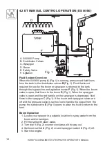
The ES 50 and ES 80 sprayers are equipped with the ET manual
control which features: on/off control for boom and handgun, pressure
adjustment, pump bypass agitation, remote pressure safety valve and
a 2-1/2” pressure gauge.
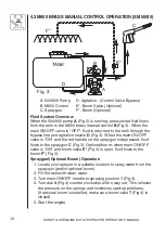
The SM 50 and SM 80 sprayers are equipped with the M600 Brass
manual control which features: on/off control for handgun/(optional
boom), pressure adjustment, pump bypass agitation, integral pressure
safety valve and a 2-1/2” pressure gauge.
The tanks, made of impact proof and chemical resistant polyethylene,
have a purposeful design with rounded contours which allows for
efficient cleaning and draining. They are designed with a large deep
sump so that they can be completely emptied even when the sprayer is
used on slopes. A drain plug is provided in the sump to assist cleaning
of the tank. The tanks are equipped with a top suction filter which can
be inspected and cleaned without emptying the tank.
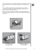
Also covered in this manual are the 6’ FD and 14’ HD booms which
feature fore and aft breakaways. The 6’ FD boom folds vertically and
the 14’ HD boom folds horizontally forward. Both booms feature ISO
flat fan nozzles with 20” spacing.
Summary of Contents for ES 50
Page 1: ...ESTATE SPRAYERS GAS ENGINE Operator s Manual 67301103 6 01 ...
Page 2: ......
Page 30: ...28 HARDI GAS ENGINE ESTATE SPRAYER OPERATOR S MANUAL 11 0 PARTS DRAWINGS 500 PUMP ...
Page 31: ...29 HARDI GAS ENGINE ESTATE SPRAYER OPERATOR S MANUAL 600 PUMP ...
Page 33: ...31 HARDI GAS ENGINE ESTATE SPRAYER OPERATOR S MANUAL PUMP FITTINGS ...
Page 34: ...32 HARDI GAS ENGINE ESTATE SPRAYER OPERATOR S MANUAL ET MANUAL CONTROL ...
Page 35: ...33 HARDI GAS ENGINE ESTATE SPRAYER OPERATOR S MANUAL M600 BRASS MANUAL CONTROL ...
Page 36: ...34 HARDI GAS ENGINE ESTATE SPRAYER OPERATOR S MANUAL ES 50 80 TANK ...
Page 37: ...35 HARDI GAS ENGINE ESTATE SPRAYER OPERATOR S MANUAL ES 50 80 FRAME ...
Page 38: ...36 HARDI GAS ENGINE ESTATE SPRAYER OPERATOR S MANUAL SM 50 80 TANK FRAME ...
Page 40: ...38 HARDI GAS ENGINE ESTATE SPRAYER OPERATOR S MANUAL 14 HD BOOM ...
Page 41: ...39 HARDI GAS ENGINE ESTATE SPRAYER OPERATOR S MANUAL SPRAYGUN ...
Page 42: ...40 HARDI GAS ENGINE ESTATE SPRAYER OPERATOR S MANUAL HOSE REEL ...
Page 45: ...43 HARDI GAS ENGINE ESTATE SPRAYER OPERATOR S MANUAL 13 0 NOTES ...
Page 46: ...44 HARDI GAS ENGINE ESTATE SPRAYER OPERATOR S MANUAL NOTES ...
Page 47: ......


