background image

E192641

ITEM #0125453

0125500

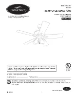
TIEMPO CEILING FAN

Español p. 19

MODEL #E-TM52BNK5CS

E-TM52BNKB5CS

ATTACH YOUR RECEIPT HERE

Serial Number

Purchase Date

1

Lowes.com/harborbreeze

Questions, problems, missing parts?

 Before returning to your retailer, call our customer 

service department at 

1-800-643-0067

, 8 a.m. - 6 p.m., EST, Monday - Thursday,  8 a.m. - 5 p.m., 

EST, Friday.

EB14350

Federal regulations require ceiling fans with light kits manufactured or imported after 
January 1, 2009, to limit total wattage consumed by the light kit to 190W.  Therefore, 
this fan is equipped with a wattage limiting device.

Harbor Breeze® is a registered trademark 
of LF, LLC. All Rights Reserved.

Summary of Contents for TIEMPO E-TM52BNK5CS

Page 1: ...your retailer call our customer service department at 1 800 643 0067 8 a m 6 p m EST Monday Thursday 8 a m 5 p m EST Friday EB14350 Federal regulations require ceiling fans with light kits manufactur...

Page 2: ...Hire a qualified electrician or consult a do it yourself wiring handbook if you are unfamiliar with installing electrical wiring Make sure the installation site you choose allows a minimum clearance...

Page 3: ...igned to accept only one 12 gauge house wire and two lead wires from the fan If your house wire is larger than 12 gauge or there is more than one house wire to connect to the corresponding fan lead wi...

Page 4: ...nopy 1 C Blade Arm 5 D Blade 5 E Motor Screw 10 preassembled 1 extra F Lock Washer 10 preassembled 1 extra G Yoke Cover 1 H Pull Chain Extension 2 H K J I E F G L M N O Q P DESCRIPTION PART I Glass Sh...

Page 5: ...ed to the building structure and can support the full weight of the fan Failure to do this can result in serious injury or death The stability of the outlet box is essential in minimizing wobble and n...

Page 6: ...FF ON OFF 3 1 Lowes com harborbreeze 7 ft min 30 in min 2 A 2 Determine mounting method to use A Standard mount B Angle mount IMPORTANT If using the angle mount ensure the ceiling angle is not steeper...

Page 7: ...Secure mounting bracket A to outlet box not included using screws spring washers and flat washers provided with the outlet box NOTE It is very important that you use the proper hardware when installin...

Page 8: ...he following manner Take the lead wires and make sure you have pulled them all the way through the top of the downrod Start at the TOP of the ball on the downrod and measure 8 in of lead wire and then...

Page 9: ...of wire within the insulation with pliers not included Repeat Step 5 for black blue if applicable and green wires 5 5 FAN MOUNTING Install ball end of downrod O into opening of mounting bracket A Ali...

Page 10: ...ct GREEN wire from fan on mounting bracket A and downrod O to BARE GREEN wire from ceiling WARNING To reduce the risk of fire electrical shock or personal injury wire connectors provided with this fan...

Page 11: ...Speed Switch For illustrative purposes only not intended to cover all types of controls 1 2 3 WIRING NOTE BLACK wire is hot power for fan BLUE wire is hot power for light kit WHITE wire is common for...

Page 12: ...ew x15 Hardware Used BB Fiber Blade Washer x15 1 Locate two canopy mounting screws K on underside of mounting bracket A and remove canopy mounting screw K closest to the open end of the mounting brack...

Page 13: ...switch housing plate M Partially loosen two screws in fitter plate on underside of motor housing J and remove the other screw Align slotted holes in switch housing plate M with loosened screws on fitt...

Page 14: ...ull chain extensions not included to the fan and light pull chains OPERATING INSTRUCTIONS The pull chain labeled SPEED has four positions to control fan speed One pull is HIGH two is MEDIUM three is L...

Page 15: ...ill effect 3B In cooler weather setting the reverse switch in the RIGHT position will result in upward airflow that can help move stagnant hot air off the ceiling area 3 Use the fan reverse switch loc...

Page 16: ...de 3 Full range dimmer switch 4 Fan is new 1 Tighten all blade screws 2 Replace blade 3 Replace with an approved speed control device 4 Allow fan a break in period of a few days especially when runnin...

Page 17: ...lifetime warranty Any service performed by an unauthorized person will render the warranty invalid Due to varying climatic conditions this warranty does not cover changes in brass finish rusting pitt...

Page 18: ...ng Bracket B Canopy C Blade Arm D Blade E Motor Screw F Lock Washer G Yoke Cover H Pull Chain Extension I Glass Shade K Canopy Mounting Screw M Switch Housing Plate N Light Kit Fitter O Downrod P Pin...

Page 19: ...ente al 1 800 643 0067 de lunes a jueves de 8 a m a 6 p m y los viernes de 8 a m a 5 p m hora est ndar del Este Los reglamentos federales requieren que los ventiladores de techo con kit de iluminaci n...

Page 20: ...n del cableado el ctrico contrate a un electricista calificado o consulte un manual de cableado para hacerlo usted mismo Aseg rese de que el sitio de instalaci n que elija permita establecer una dist...

Page 21: ...oportar solo un cable de la casa de calibre 12 y dos cables conductores del ventilador Si el conductor de la casa es de un calibre superior a 12 o hay m s de un conductor de la casa para conectar a lo...

Page 22: ...r 10 preensamblado 1 adicional F Arandela de seguridad 10 preensamblada 1 adicional G Cubierta de la horquilla 1 H Extensi n para la cadena 2 de tiro DESCRIPCI N PIEZA I Pantalla de vidrio 4 J Carcasa...

Page 23: ...ntilador El incumplimiento de dicho paso podr a provocar lesiones graves o la muerte La estabilidad de la caja de salida es fundamental para minimizar el tambaleo y el ruido en el ventilador una vez q...

Page 24: ...es com harborbreeze 2 13 m 7 pies m n 76 2 cm 30 pulg m n 2 A 2 Determine el m todo de instalaci n que utilizar A Montaje est ndar B Montaje en ngulo IMPORTANTE Si realiza el montaje en ngulo verifiqu...

Page 25: ...n preensamblados 5 1 Asegure el soporte de montaje A a la caja de salida no se incluye con los tornillos las arandelas de resorte y las arandelas planas que se incluyen en la caja de salida NOTA Es p...

Page 26: ...erlo de la siguiente manera Sujete los cables conductores y aseg rese de jalarlos completamente a trav s de la parte superior de la varilla Comience en la parte SUPERIOR de la bola en la varilla y mid...

Page 27: ...n pinzas no se incluyen Repita el paso 5 para los conductores negro azul si corresponde y verde 5 5 MONTAJE DEL VENTILADOR Instale el extremo con la bola de la varilla O en la abertura del soporte de...

Page 28: ...rte de montaje A y la varilla O al conductor DESNUDO VERDE del techo ADVERTENCIA Para reducir el riesgo de incendios descargas el ctricas o lesiones personales los conectores de cables proporcionados...

Page 29: ...Solo con fines ilustrativos No pretende cubrir todos los tipos de controles 1 2 3 CABLEADO NOTA El conductor NEGRO es el que proporciona alimentaci n al ventilador El conductor AZUL es el que proporci...

Page 30: ...dela del aspa de fibra x15 1 Ubique dos tornillos de montaje de la base K debajo del soporte de montaje A y retire el tornillo de montaje de la base K m s cercano al extremo abierto del soporte de mon...

Page 31: ...tornillos de la placa de soporte en la parte inferior de la carcasa del motor J y retire el otro tornillo Alinee los orificios ranurados en la placa de la carcasa del interruptor M con los tornillos...

Page 32: ...del ventilador y la luz INSTRUCCIONES DE FUNCIONAMIENTO La cadena de tiro marcada como SPEED VELOCIDAD tiene cuatro posiciones para controlar la velocidad del ventilador Jale una vez para la posici n...

Page 33: ...nto refrescante 3B En climas m s fr os la configuraci n del interruptor de reversa en la posici n a la DERECHA crear un flujo de aire ascendente que puede ayudar a mover el aire caliente estancado fue...

Page 34: ...nuevo 1 Apriete todos los tornillos de las aspas 2 Reemplace la hoja 3 Reemplace por un dispositivo de control de velocidad autorizado 4 Permita que el ventilador tenga un per odo de asentamiento de...

Page 35: ...e la garant a limitada de por vida Cualquier servicio realizado por una persona no autorizada invalidar la garant a Debido a las cambiantes condiciones clim ticas esta garant a no cubre cambios en el...

Page 36: ...D Aspa E Tornillo del motor F Arandela de seguridad G Cubierta de la horquilla H Extensi n para la cadena de tiro I Pantalla de vidrio K Tornillo de montaje de la base M Placa de la carcasa del interr...

Page 37: ...EXPLODED VIEW VISTA DETALLADA QUICK REFERENCE GUIDE GU A DE REFERENCIA R PIDA B C E I F A CC AA BB H J G L M N O Q P R D K...

Page 38: ...u a de referencia r pida This is a general overview of assembly process Read the complete installation manual for detailed instructions and safety information Este es un resumen general del proceso de...

Page 39: ...Instale el soporte de montaje MONTAJE EST NDAR Extremo abierto MONTAJE EN NGULO DESCRIPCI N GENERAL DE LA INSTALACI N Instale las aspas Instale el kit de iluminaci n y la bombillas Cuelgue el ventilad...

Page 40: ...A DE REFERENCIA R PIDA or o Turn On Power Source Turn on power source Turn On Power Source 10 7 6 3 2 14 32 12 30 12 30 8 26 8 26 Install Pull Chain Extensions DESCRIPCI N GENERAL DE LA INSTALACI N P...

Reviews: