background image

7

INITIAL INSTALLATION

DOWNROD-STYLE FAN MOUNTING

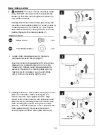
Remove pin (N) and clip (O) from downrod (A).

Partially loosen preassembled set screw and nut 
in yoke at top of motor housing (D).

 1a.

 1b.

5.

D

1b

Yoke

Set Screw

    & Nut

Sideview

1a

O

N

A

A

 2.

2

B

E

5

D

Motor

Block

S

Remove motor screw/washers (S) from 
underside of motor housing (D) and save for 
blade arm attachment later on. [If there are 
plastic motor blocks installed with the motor 
screws/washers (S), discard the plastic motor 
blocks.] 

For 

DOWNROD-STYLE FAN MOUNTING

proceed to step 1a below.

For 

CLOSEMOUNT-STYLE FAN MOUNTING

skip to page 9.

Insert downrod (A) through canopy (B) and yoke 
cover (E).Thread wires from motor housing (D) up 
through downrod (A). 

Summary of Contents for TALAMORE TAL60BNK8LR

Page 1: ...Espa ol p 20 MODEL TAL60BNK8LR ATTACH YOUR RECEIPT HERE Purchase Date 1 4007498 Questions problems missing parts Before returning to your retailer call our customer service department at 1 800 527 129...

Page 2: ...ent The equipment refers to the remote control transmittor and or LED light kit This device complies with Part 15 of the FCC Rules Operation is subject to the following two conditions 1 this device ma...

Page 3: ...reduce the risk of fire electrical shock or personal injury wire connectors provided with this fan are designed to accept only one 12 gauge house wire and two lead wires from the fan If your house wi...

Page 4: ...1 G Canopy Mounting Screw 4 preassembled H Fitter Plate 1 I Fitter Plate Screw 3 preassembled J Blade 8 DESCRIPTION PART QUANTITY DESCRIPTION PART QUANTITY K Motor Plate Screw 3 preassembled L Blade A...

Page 5: ...quired for Assembly not included Electrical Tape Phillips Screwdriver Pliers Safety Glasses Stepladder and Wire Strippers Helpful Tools not included AC Tester Light Tape Measure Do It Yourself Wiring...

Page 6: ...ecessary to ensure proper blade clearance Closemount mounting is more suitable for ceilings lower than 8 ft high Check to make sure blades J will be at least 30 in from any obstruction and at least 7...

Page 7: ...tor Block S Remove motor screw washers S from underside of motor housing D and save for blade arm attachment later on If there are plastic motor blocks installed with the motor screws washers S discar...

Page 8: ...8 in of lead wire and then cut the excess wire off with wire cutters not included NOTE If you do not cut back the lead wires Steps 4 and 5 are not necessary and you may proceed to Step 6 instead E Sli...

Page 9: ...to WIRING on page 11 C Tab 6 A Slot 2 D Screw Lock Washer Remove every other preassembled screw and lock washer from top of motor housing D Remove preassembled canopy cover P from bottom of canopy C N...

Page 10: ...ounting bracket C using one of the non slotted holes in the canopy B 3 3 Non Slotted Tab C 3 B Pull wires up through hole in the middle of the canopy B and attach canopy B to motor housing D using the...

Page 11: ...UND GREEN OR BARE BLACK FROM RECEIVER FROM FAN FROM RECEIVER FROM CEILING A C GREEN GROUND WARNING To reduce the risk of fire electrical shock or personal injury wire connectors provided with this fan...

Page 12: ...wire WARNING Make sure no bare wire or wire strands are visible after making connections Place GREEN and WHITE connections on opposite side of the outlet box from the BLACK and BLUE if applicable con...

Page 13: ...usly removed Step 5 page 7 Insert two motor screws washers S through one blade arm L to attach blade arm L to motor housing D Tighten motor screws washers S securely Repeat with remaining blade arms L...

Page 14: ...t F to BLUE or BLACK wire from motor housing D Make sure molex connections are secure F 6 WHITE BLUE or BLACK WHITE BLUE D H 7 Carefully arrange wiring within the fitter plate H to ensure wires do not...

Page 15: ...drill two pilot holes in drywall at marked locations Position plastic anchor in each pilot hole Gently tap plastic anchors with a hammer not included until flush with wall surface Screw bracket screws...

Page 16: ...arty responsible for compliance could void the user s authority to operate the equipment This device complies with Part 15 of the FCC Rules Operation is subject to the following two conditions 1 this...

Page 17: ...e light kit for 5 minutes every 2 hours Color mode change select light color warm white bright warm white natural white bright white daylight 3 1 2 4 5 6 7 8 OPERATING INSTRUCTIONS Tap button quickly...

Page 18: ...securely mounted 4 Fan too close to vaulted ceiling 5 Set screw on motor housing yoke is not tightened properly 6 Set screw on hanging ball is not tightened properly 1 Tighten all blade screws 2 Swit...

Page 19: ...fans maintain their beauty when protected from varying weather conditions Any glass provided with this fan is not covered by the warranty Any replacement of defective parts for the ceiling fan must be...

Reviews: