J
A
14
LIGHT KIT INSTALLATION
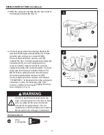
1. Remove one of the three screws in the
adapter plate of motor assembly (A). Slightly
loosen the remaining two screws. Assemble
the housing upper assembly (I) to the fan
motor assembly (A) using the two key slots.
Replace the third screw and secure all three
screws. (Fig. 1)
A
3. Remove one of the three screws in the
housing upper assembly (I). Slightly loosen the
reamining two screws. Assemble the light
socket plate (J) to the housing upper assembly
(I) using the two key slots. Replace the third
screw and securely tighten all three screws.
(Fig. 3)
3
J
2. Connect the 2-pin connector from the light
socket plate assembly (J) to 2-pin connector
from motor assembly (A). (Fig. 2)
I
1
2
I


