background image

10

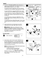
WIRING

Wrap electrical tape (not included) around each 
individual wire connector (AA) down to the wire. 


WARNING:

 Make sure no bare wire or wire 

strands are visible after making connections. Place 
GREEN and WHITE connections on opposite side of 
the outlet box from the BLACK and BLUE (if 
applicable) connections.

 2. 

2

Hardware Used

Wire Connector

x 3

AA

AA

AA

AA

3

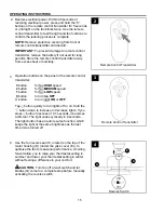
Gently slide remote control receiver (R) flat-side up 
into mounting bracket (C). Turn spliced/taped wires 
upward and gently push wires and wire connectors 
(CC) into outlet box. Let antenna from remote control 
receiver (R) hang to the side.

NOTE:

 The remote control included with this fan meets 

the following requirements:
 

a.

 Not for use with solid state fans.


b.

 Electrical rating: 120V / 60 Hz;


          motor amps:1.25 MAX.

Should you choose to use a different remote control 
with this fan, it must also meet these same 
requirements.

 3. 

Antenna

A

R

C

(1.)  Connect all GROUND (GREEN) wires from fan (on 

downrod (A), if applicable, and mounting bracket (C)) to 
BARE/GREEN supply wire from ceiling.

 
Connect BLACK wire (labeled AC IN L) from remote 
control receiver (R) to BLACK supply wire from ceiling.

 
Connect WHITE wire (labeled AC IN N) from remote 
control receiver (R) to WHITE supply wire from ceiling.

 
Connect WHITE wire (labeled TO MOTOR N) from 
remote control receiver (R) to WHITE wire from motor 
housing (D).

 
Connect BLACK wire (labeled TO MOTOR L) from 
remote control receiver (R) to BLACK wire from motor 
housing (D).

 
Connect BLUE wire (labeled FOR LIGHT) from remote 
control receiver (O) to BLUE wire from motor housing 
(D).

R

1

WHITE SUPPLY WIRE

BLACK SUPPLY WIRE

BLACK

BLACK

WHITE

BLUE

BLUE

WHITE

BLACK

AC IN L

WHITE

AC IN N

WHITE

GROUND (GREEN OR BARE)

GROUND 

(GREEN OR BARE)

BLACK

FROM
RECEIVER

FROM 
FAN

FROM
RECEIVER

FROM
CEILING

AA

AA

A

C

Summary of Contents for FAIRWIND

Page 1: ...LW3LRS Questions problems missing parts Before returning to your retailer call our customer service department at 1 800 527 1292 8 30 a m 5 p m CST Monday Friday ATTACH YOUR RECEIPT HERE Serial Number...

Page 2: ...30 in from the end of the blades to any obstruction After you install the fan make sure all connections are secure to prevent the fan from falling The net weight of this fan including the light kit is...

Page 3: ...ne house wire to connect to the corresponding fan lead wires consult an electrician for the proper size wire connectors to use To reduce the risk of fire or electrical shock do not use the fan with an...

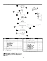
Page 4: ...Cover 1 F Light Kit Fitter 1 G Blade 3 H Canopy Cover 1 I Glass Shade 1 J Blade Plate 3 DESCRIPTION PART QUANTITY PACKAGE CONTENTS 4 E N O DESCRIPTION PART QUANTITY K Canopy Mounting Screw 2 preassemb...

Page 5: ...e contents list If any part is missing or damaged do not attempt to install operate or assemble the product Estimated Assembly Time 120 minutes Tools Required for Assembly not included Electrical Tape...

Page 6: ...eiling angle is not steeper than 19 Helpful Hint Downrod style mounting is best suited for ceilings 8 ft high or higher For taller ceilings you may want to use a longer downrod not included Angle styl...

Page 7: ...en thread wires from motor housing D through downrod A 6 B E A H 4 Open End 4 C C ANGLE MOUNT STANDARD MOUNT Secure mounting bracket C to outlet box not included using screws spring washers and flat w...

Page 8: ...E If you do not cut back the lead wires Steps 8 and 9 are not necessary and you may proceed to Step 10 instead 8 7 Slip downrod A into motor housing yoke align holes and re install pin L and clip M Ti...

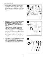
Page 9: ...s to use CAUTION Be sure outlet box is properly grounded and that a ground green or bare wire is present WARNING If house wires are different colors than referred to in the following steps stop immedi...

Page 10: ...ose to use a different remote control with this fan it must also meet these same requirements 3 Antenna A R C 1 Connect all GROUND GREEN wires from fan on downrod A if applicable and mounting bracket...

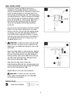
Page 11: ...proceeding 11 FINAL INSTALLATION 2 2 G J D BB Hardware Used Blade Screw Washer x 6 BB Locate two canopy mounting screws K on underside of mounting bracket C and remove canopy mounting screw K closest...

Page 12: ...te screw O Align slotted holes in fitter plate N with loosened motor plate screws O allowing molex connections from motor housing D to come through hole in fitter plate N Twist fitter plate N to lock...

Page 13: ...o ensure wires do not get pinched when attaching the light kit fitter F Align slotted holes in light kit fitter F with loosened fitter plate screws P on fitter plate N Twist light kit fitter F to lock...

Page 14: ...ser is encouraged to try to correct the interference by one or more of the following measures Reorient or relocate the receiving antenna Increase the separation between the equipment and receiver Conn...

Page 15: ...utton for fan MEDIUM speed 1 button for fan LOW speed 0 button to turn fan OFF button to turn light ON or OFF Tap button quickly to turn lights off or on Hold the button down to increase or decrease l...

Page 16: ...osition will result in upward airflow that can help move stagnant hot air off the ceiling area At least twice each year lower canopy B to check downrod A assembly and tighten all screws on fan Clean m...

Page 17: ...e 2 Unbalanced blades 3 Fan not securely mounted 4 Fan too close to vaulted ceiling 5 Set screw s on motor housing yoke is are not tightened properly 6 Set screw on hanging ball is not tightened prope...

Page 18: ...anty does not cover changes in brass finish rusting pitting tarnishing corroding or peeling Brass finish fans maintain their beauty when protected from varying weather conditions Any glass provided wi...

Reviews: