background image

5

INITIAL INSTALLATION


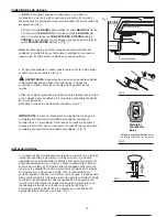
1. Turn off circuit breakers and wall switch to the fan supply line leads. 
(Fig. 1)


DANGER:

 Failure to disconnect power supply prior to installation 

may result in serious injury or death.

3. Check to make sure blades (H) are at least 30 in. from any 
obstruction. Check downrod (A) length to ensure blades (H) are at 
least 7 ft. above the floor. (Fig. 3)

2. Determine mounting method to use. (Fig. 2)
    

A.

 Normal mount


B.

 Angle mount

IMPORTANT: 

If using the angle mount, check to make sure the 

ceiling angle is not steeper than 19°.

4. Secure mounting bracket (C) to outlet box using screws, spring 
washers, and flat washers provided with the outlet box. (Fig. 4)
*

Note: It is very important that you use the proper hardware when 

installing the mounting bracket (C) as this will support the fan.

IMPORTANT:

 If using the angle mount, make sure open end of 

mounting bracket (C) is installed facing the higher point of the ceiling.

PREPARATION

 1

.

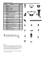
 Before beginning assembly and installation of product, make sure all parts are present. Compare parts with 

“Package Contents” list and diagrams on the previous page. If any part is missing or damaged, do not attempt to 
assemble, install or operate the product. Contact customer service for replacement parts as indicated at the bottom 
of page 4.

Estimated Assembly Time:


120


minutes

Tools Required for Assembly 

(not included)

:


electrical tape, Phillips screwdriver, pliers, safety glasses, stepladder 

and wire strippers

Helpful Tools 

(not included)

:


AC tester light, tape measure, do-it-yourself-wiring handbook

, available at Lowe’s,

 and 

wire cutters

Bulbs Required 

(included)

:

 4 candelabra base 15-watt max. bulbs, for up-light 


 3 halogen 50-watt max. bulbs, size GU10, for light kit


        DANGER:

 When using an existing outlet box, make sure the box is securely attached to the building structure 

and can support the full weight of the fan. Failure to do this can result in serious injury or death.

 The stability of the 

outlet box is essential in minimizing wobble and noise in the fan after installation is complete. 


CAUTION:

 Be sure outlet box is properly grounded and that a ground wire (green or bare) is present.

2. After opening top of carton, remove mounting hardware package from foam inserts. Remove motor from packing 
and place on carpet or on foam to avoid damage to finish.


CAUTION:

 Carefully check all screws, bolts and nuts on fan motor assembly to ensure that they are secured.

Fig. 1

Fig. 2

Fig. 3

7 ft.
min.

30 in.

min.

H

A

B

Fig. 4

C

Summary of Contents for E-GAL52BC4GRS

Page 1: ...e or control fan speed with a full range dimmer switch WARNING To reduce the risk of fire electrical shock or personal injury do not bend the blade arms when installing them balancing the blades or cleaning the fan Do not insert foreign objects between the rotating fan blades Mount to outlet box marked ACCEPTABLE FOR FAN SUPPORT and use mounting screws provided with the outlet box Most outlet boxe...

Page 2: ...ntents 4 Preparation 5 Initial Installation 5 Fan Mounting 6 Wiring 6 Final Installation 7 9 Remote Control Operation 9 Automated Learning Process Activating Code 10 Bulb Replacement for Up light 10 Care and Maintenance 10 Troubleshooting 11 Warranty 12 ...

Page 3: ...ox Most outlet boxes commonly used for the support of lighting fixtures are not acceptable for fan support and may need to be replaced Consult a qualified electrician if in doubt Secure the outlet box directly to the building structure The outlet box and its support must be able to support the moving weight of the fan at least 35 lbs Do NOT use a plastic outlet box 7 After you install the fan make...

Page 4: ...n in motor housing yoke 1 N Clip attached to pin 1 O 1 5 volt AA Battery in hardware pack 2 P Remote Control Transmitter 1 Q Cap in hardware pack 1 R Halogen Bulb for light kit 3 S Canopy Cover in hardware pack 1 A B C D E F G H I J K L M N O P Q R NOTE For replacement parts call our customer service department at 1 800 527 1292 8 30 a m 5 00 p m CST Monday Friday When ordering parts please have t...

Page 5: ...amaged do not attempt to assemble install or operate the product Contact customer service for replacement parts as indicated at the bottom of page 4 Estimated Assembly Time 120 minutes Tools Required for Assembly not included electrical tape Phillips screwdriver pliers safety glasses stepladder and wire strippers Helpful Tools not included AC tester light tape measure do it yourself wiring handboo...

Page 6: ...s than referred to in the following steps stop immediately A professional electrician is recommended to determine wiring 1 Remove pin M and clip N from motor housing yoke at top of motor housing E and partially loosen set screws Fig 1 Helpful Hint Downrod style mounting is best suited for ceilings 8 ft 2 44 m high or higher For taller ceilings you may want to use a longer downrod sold separately t...

Page 7: ...ctions Turn spliced taped wires upward and gently push wires and wire connectors K into outlet box IMPORTANT Using a full range dimmer switch to control fan speed will cause a loud humming noise from fan To reduce the risk of fire or electrical shock do NOT use a full range dimmer switch to control fan speed Fig 3 K K K Fig 3 Fig 2 Dimmer Switch For illustrative purposes only not intended to cover...

Page 8: ... openings on blade band aligning holes in blade H with holes located inside motor housing E Note Turn blade band in order to align insert blade screws I and blade washers J Insert three blade screws I along with blade washers J and then tighten blade screws I securely with a Phillips screwdriver Fig 3 Repeat procedure for each remaining blade H Fitter Plate Blade Band 4 Remove three screws from fi...

Page 9: ...ton for light BRIGHTNESS and OFF lower light REV button to REVERSE blade direction fan must be on low before reversing blade direction The light function is controlled by pressing the UP and or DOWN button Tap either UP or DOWN button quickly to turn lights off or on Hold DOWN button down to increase or decrease lights If you press DOWN button in excess of 0 7 seconds it becomes a dimmer The light...

Page 10: ...ammed to multiple receivers or fans If this is not desired turn wall switch off to any other programmable receiver or fan 1 Locate the two batteries O and then remove plastic that is wrapped around batteries O Remove battery cover from back side of transmitter P Install the two 1 5 volt AA batteries O provided refer to drawing at right 2 Locate dimmer switch in the top left part of the battery com...

Page 11: ...osen canopy B and verify that mounting bracket C is secure 4 Fan too close to vaulted ceiling 4 Use a longer downrod A or move fan to another location 5 Set screw s on motor housing 5 Tighten yoke set screw s securely yoke is are not tightened properly 6 Set screw on hanging ball is not 6 Carefully loosen and lower screw on tightened properly canopy B and verify that set screw on hanging ball is t...

Page 12: ...ons this warranty does not cover changes in brass finish rusting pitting tarnishing corroding or peeling Brass finish fans maintain their beauty when protected from varying weather conditions Any glass provided with this fan is not covered by the warranty Any replacement of defective parts for the ceiling fan must be reported within the first year from the date of purchase For the balance of the w...

Page 13: ...erruptor con reductor de luz de gama completa ADVERTENCIA Para reducir el riesgo de incendio choque eléctrico o lesión personal no doble los brazos de las paletas mientras las esté instalando ni cuando esté balanceando las paletas ni cuando esté limpiando el ventilador No inserte objetos extraños entre las paletas giratorias del ventilador Sujete a una caja de salida marcada Aceptable para sostene...

Page 14: ...ón inicial 17 Montaje del ventilador 18 Conexión de los cables 18 19 Instalación final 19 21 Funcionamiento del control remoto 21 Proceso de aprendizaje automático El activar el código 22 Reemplazo de bombillas de la luz superior 22 Cuidado y mantenimiento 22 Localización de fallas 23 24 Garantía 24 ...

Page 15: ...las cajas de salida que se usan comúnmente para sostener aparatos de alumbrado no son aceptables para sostener ventiladores y es posible que sea necesario reemplazarla Consulte con un electricista calificado si tiene alguna duda Asegure la caja de salida directamente a la estructura del edificio La caja de salida y el soporte deben ser capaces de sostener el peso móvil del ventilador por lo menos ...

Page 16: ...r del motor 1 N Sujetador sujetado a la clavija 1 O Batería de 1 5 voltios tamaño AA 2 en paquete de artículos de ferretería P Transmisor del control remoto 1 Q Tapa en paquete de artículos de ferretería 1 R Bombilla halógena 3 para el juego de luz S Decoración para la cubierta 1 en paquete de artículos de ferretería CONTENIDO DEL PAQUETE RECORDATORIO IMPORTANTE Se tienen que utilizar las piezas p...

Page 17: ...e de que la caja esté firmemente sujetada a la estructura del edificio para que pueda sostener el peso total del ventilador El no hacer ésto puede resultar en graves daños o la muerte La estabilidad de la caja de salida es esencial para minimizar tambaleo y ruido en el ventilador una vez que se haya terminado la instalación PRECAUCION Asegúrese de que la caja de salida esté conectada a tierra corr...

Page 18: ...s diferentes a los mencionados en los siguientes pasos suspenda el trabajo inmediatamente Se recomienda que un electricista profesional determine la instalación eléctrica que se debe hacer Fig 4 C bola B A 1 Quite la clavija M y el sujetador N del yugo del bastidor del motor en la parte superior del bastidor del motor E y parcialmente afloje los tornillos de fijación Fig 1 Consejo útil El montaje ...

Page 19: ...brir todo tipo de control Nota El cable negro es positivo conduce energía eléctrica del ventilador El cable blanco es tanto para el ventilador como para el juego de luz El cable verde o pelado es el que hace tierra Fig 1 INSTALACION FINAL A S B L 1 Localice los dos tornillos para montaje de la cubierta L en la parte inferior del soporte de montaje C y quite el tornillo L que está localizado más ce...

Page 20: ... para las paletas alineando los agujeros en la paleta con los agujeros localizados dentro del bastidor del motor E Nota Gire la banda para las paletas para alinear introducir los tornillos para las paletas I y las arandelas para las paletas J Introduzca tres tornillos para las paletas I junto con las arandelas para las paletas J y luego apriételos bien con un destornillador Phillips Fig 3 Repita e...

Page 21: ...Botón DOWN para controlar la BRILLANTEZ de la luz inferior y para APAGARLA Botón REV para CAMBIAR la dirección de las aspas hay que poner el ventilador en posición baja antes de poner el ventilador en reversa La función de la luz se controla oprimiendo los botones de la luz UP o DOWN Toque el botón rápido para apagar y prender la s luz luces Oprima el botón DOWN y manténgalo oprimido para aumentar...

Page 22: ... varios receptores o ventiladores Si no desea hacer esto apague el interruptor de pared de cualquier otro receptor o ventilador programable 1 Localice las dos baterías O y luego quite el plástico con el cual están envueltas Quite la cubierta de la batería de la parte de atrás del transmisor P e instale las dos baterías O de 1 5 voltios tamaño AA provistas refiérase al dibujo al lado 2 Localice el ...

Page 23: ...a bien cubierta B cuidadosamente y verifique que el soporte de montaje C esté bien sujeto 4 El ventilador está demasiado 4 Utilice un vástago A más largo cerca de un techo abovedado o mueva el ventilador a otro lugar 5 No se apretó apretaron bien el 5 Apriete bien el los tornillo s de los tornillo s de fijación en el fijación yugo del bastidor del motor 6 No se apretó bien el tornillo de 6 Afloje ...

Page 24: ...acabado bronce protegiéndolo de las diversas condiciones de clima Las pantallas provistas con el ventilador no están cubiertas por la garantía Cualquier pieza defectuosa del ventilador de techo se debe reportar dentro del primer año desde la fecha de compra Si desea que reparemos o reemplacemos su ventilador llame a nuestro departamento de servicio al cliente al 1 800 527 1292 para obtener una aut...

Reviews: