background image

43

Lowes.com/harborbreeze

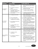
SOLUCIÓN DE PROBLEMAS

PROBLEMA

CAUSA POSIBLE

ACCIÓN CORRECTIVA

El ventilador no 

se mueve.

1.  El interruptor de reversa no 

está activado. 

2.  El interruptor de pared se 

apagó.

3.  No hay suministro de 

electricidad o hay un fusible 

(interruptor) quemado.

4.  Una conexión de los cables no 

es la correcta.

1. 

Mueva firmemente el interruptor de 

reversa hacia la izquierda o hacia la 

derecha.

2.  Asegúrese de que el interruptor de 

pared esté encendido.

3.  Encienda el suministro eléctrico 

o verifique el fusible (interruptor).


4.  Desactive la alimentación eléctrica 

y revise todas las conexiones de la 

caja de salida del techo.

El ventilador 

hace ruido.

1.  Las aspas están sueltas. 


2.  Hay una aspa partida.
3.  El control de pared no es 

compatible con el ventilador. 

4.  No se supera el período de 

asentamiento. 


5.  La caja de salida no está 

asegurada.

6.  La abrazadera de montaje no 

está asegurada.

1.  Revise y apriete todos los tornillos que 

sostienen las aspas del ventilador en 

los brazos de las aspas y en el motor.

2.  Reemplace la aspa partida.
3.  No use un regulador de intensidad 

de rango completo para controlar la 

velocidad del ventilador.

4.  Haga funcionar el ventilador de 24 a 

48 horas continuamente a velocidad 

media o alta durante el período de 

“asentamiento”.

5.  Revise que la caja de salida esté 

asegurada a la estructura del edificio.

6.  Asegúrese de que la abrazadera de 

montaje esté fija en la caja de salida 

y que los tornillos estén apretados.

Hay un tambaleo 

excesivo.

1. 

Una o varias aspas están flojas.


2.  Las aspas no están 

equilibradas. 


3.  El montaje del ventilador no 

está asegurado. 

1.  Revise y apriete todos los tornillos que 

sostienen las aspas del ventilador en 

los brazos de las aspas y en el motor.

2.  Intercambie un aspa con otra del lado 

opuesto. O equilibre el ventilador 

mediante el kit de equilibrio (no se 

incluye).

3.  Desconecte el suministro de 

electricidad. Afloje la base y verifique 

que la abrazadera de montaje esté 

asegurada en la caja de salida 

eléctrica. La abrazadera debe estar 

al ras de la caja de salida y no debe 

moverse.

Summary of Contents for CENTREVILLE 40117

Page 1: ...T Monday Thursday 8 a m 5 p m EST Friday 1 ATTACH YOUR RECEIPT HERE Serial Number _________________________ Purchase Date _________________________ Lowes com harborbreeze Harbor Breeze is a registered...

Page 2: ...3 Hardware Contents 4 Safety Information 5 Preparation 6 Initial Installation 7 Wiring 10 Final Installation 13 Using the Fan With No Light Kit Option 17 Operating Instructions 18 Care and Maintenance...

Page 3: ...A Motor Housing 1 B Upper Mounting Bracket 1 C Extra Switch Housing 1 D Motor Assembly 1 E Light Kit Fitter 1 F Twist On Glass Shade 3 G Blade Arm 5 H Blade 5 I Bulb 3 J Switch Housing Plate preassemb...

Page 4: ...Pull Chain Extension Qty 2 Motor Screw Qty 10 1 extra preassembled to Motor Housing A Motor Housing Mounting Screw Qty 4 preassembled to Mounting Bracket B Light Kit Screw Qty 3 preassembled to Switch...

Page 5: ...ch to control fan speed will cause a loud humming noise from the fan To reduce the risk of fire or electric shock do NOT use a full range dimmer switch to control the fan speed WARNING To reduce the r...

Page 6: ...at all parts are present Compare all parts with the package contents list and hardware contents list If any part is missing or damaged do not attempt to assemble the product After opening the top of t...

Page 7: ...ury or death 1 2 Check to make sure the blades H are at least 30 in from any obstruction and at least 7 ft above the floor 2 7 ft min 30 in min H 3 Secure the upper mounting bracket B to the outlet bo...

Page 8: ...e Used EE Motor Screw x 10 4 EE D 5 Remove the bracket screws HH from underneath the lower mounting bracket K Hardware Used HH Bracket Screw x 4 HH K 5 6 Place a tab on the lower mounting bracket K in...

Page 9: ...INITIAL INSTALLATION 7 Reinstall the previously removed bracket screws HH underneath the lower mounting bracket K and into the upper mounting bracket B Securely tighten the screws Hardware Used HH Br...

Page 10: ...and Blue wires from the fan to the Black wire from the ceiling Connect the White wire from the fan to the White wire from the ceiling Connect all Ground Green wires together from the fan to the Bare G...

Page 11: ...ct all Ground Green wires together from the fan to the Bare Green wire from the ceiling Secure all wiring connections together with wire connectors CC Note The Black wire is hot power for the fan The...

Page 12: ...connections Place the Green and White wire connections on opposite sides of the outlet box from the Black and Blue if applicable wire connections CC 3 Important Using a full range dimmer switch not i...

Page 13: ...ted holes Remove the other two motor housing mounting screws FF from opposite sides of the mounting bracket B Hardware Used FF Motor Housing Mounting Screw x 4 B A FF FF 1 2 Slide the motor housing A...

Page 14: ...t this step with each blade Hardware Used AA Blade Screw x 15 BB Fiber Blade Washer x 15 AA BB G H 3 4 Align a blade arm G and a blade isolator II with two holes underneath the motor D and insert two...

Page 15: ...er E to the Blue wire from the switch housing plate J Ensure that the connections are secure for all wires Hardware Used GG Light Kit Screw x 3 Note If you do not wish to use the light kit proceed to...

Page 16: ...tall three candelabra base 60 watt max bulbs I included Important When you need to replace bulbs please allow bulbs and glass shades to cool down before handling them I 8 9 Attach the pull chain exten...

Page 17: ...C with the holes in the light kit screws GG The wide gap in the top edge of the extra switch housing C should align with the reverse switch on the switch housing plate J for the proper fit Re insert...

Page 18: ...2 The pull chain in the center is used to turn the light ON and OFF DD J 2 3 Use the fan reverse switch located on the switch housing plate J to optimize your fan for seasonal performance A ceiling f...

Page 19: ...ft or the right in or der for the fan to function If the reverse switch is set in the middle position the fan will not operate Fig 3A Fig 3B 3 CARE AND MAINTENANCE At least twice each year lower the c...

Page 20: ...all screws that hold the fan blades to the blade arms and the motor 2 Replace the cracked blade 3 Do not use a full range dimmer switch to control the fan speed 4 Run the fan continuously for 24 48 h...

Page 21: ...installed correctly 2 The light kit wire plugs are not connected properly 3 There is a faulty wire connection 1 Re install the bulb s 2 Ensure that the male and female plugs in the light kit fitter ar...

Page 22: ...lid Due to varying climate conditions this warranty does not cover any changes in brass finish including rusting pitting corroding tarnishing or peeling Brass finishes of this type give their longest...

Page 23: ...ng parts please have the Model or Item of the fan available PART DESCRIPTION MODEL 40117 PART MODEL 40118 PART MODEL 40119 PART A Motor Housing 0403517 A 0403518 A 0403519 A B Upper Mounting Bracket 0...

Page 24: ...m y los viernes de 8 a m a 5 p m hora est ndar del Este 24 ADJUNTE SU RECIBO AQU N mero de serie _________________________ Fecha de compra _________________________ Lowes com harborbreeze Harbor Breez...

Page 25: ...dad 28 Preparaci n 29 Instalaci n inicial 30 Cableado 33 Instalaci n final 36 C mo usar el ventilador sin la opci n del kit de iluminaci n 40 Instrucciones de funcionamiento 41 Cuidado y mantenimiento...

Page 26: ...uperior 1 C Carcasa del interruptor extra 1 D Ensamble del motor 1 E Soporte del kit de iluminaci n 1 F Pantalla de vidrio giratoria 3 G Brazo del aspa 5 H Aspa 5 I Bombilla 3 J Placa de la carcasa de...

Page 27: ...del motor Cant 10 y 1 adicional preensamblado en la carcasa del motor A Tornillo de montaje de la carcasa del motor Cant 4 preensamblado en la abrazadera de montaje B Tornillo para el kit de iluminac...

Page 28: ...bido intenso del ventilador Para reducir el riesgo de incendios o descargas el ctricas NO use un regulador de intensidad de rango completo para controlar la velocidad del ventilador ADVERTENCIA Para r...

Page 29: ...e tener todas las piezas Compare todas las piezas con la lista del contenido del paquete y con la lista de aditamentos No intente ensamblar el producto si falta alguna pieza o si estas est n da adas D...

Page 30: ...aves o la muerte 1 2 Compruebe que las aspas H est n al menos a 76 20 cm de cualquier obst culo y al menos a 2 13 m del piso 2 2 13 m m n 76 20 cm m n H 3 Asegure la abrazadera superior de montaje B a...

Page 31: ...5 Retire los tornillos de la abrazadera HH debajo de la abrazadera inferior de montaje K Aditamentos utilizados HH Tornillo de abrazadera x 4 HH K 5 6 Coloque una leng eta de la abrazadera inferior d...

Page 32: ...va a instalar los tornillos de la abrazadera previamente retirados HH debajo de la abrazadera inferior de montaje K y en la abrazadera superior de montaje B Apriete firmemente los tornillos Aditamento...

Page 33: ...TIRO Conecte los conductores negro y azul del ventilador al conductor negro del techo Conecte el cable blanco del ventilador al cable blanco del techo Conecte todos los cables de tierra verdes juntos...

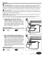
Page 34: ...cable desnudo o verde del techo Asegure todas las conexiones del cableado junto con los conectores de cable CC Nota El cable negro le proporciona energ a al ventilador El cable azul le proporciona en...

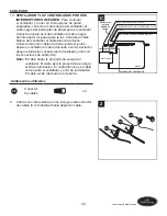
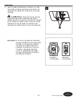
Page 35: ...las conexiones de cables verde y blanco en el lado opuesto de la caja de salida con respecto a las conexiones de cables negro y azul si corresponde CC 3 Importante El uso de un regulador de intensida...

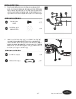
Page 36: ...s tornillos de montaje de la carcasa del motor FF de los costados opuestos de la abrazadera de montaje B Aditamentos utilizados FF Tornillo de montaje de la carcasa del motor x 4 B A FF FF 1 2 Desplac...

Page 37: ...cada aspa Aditamentos utilizados AA Tornillo para aspa x 15 BB Arandela para aspa de fibra x 15 AA BB G H 3 4 Alinee el brazo del aspa G y el aislador de aspa II con dos orificios debajo del motor D...

Page 38: ...rese de que todas las conexiones sean seguras para todos los cables Aditamentos utilizados GG Tornillo para el kit de iluminaci n x 3 Nota Si no desea usar el kit de iluminaci n consulte la secci n C...

Page 39: ...o de 60 vatios como m ximo I incluidas Importante Cuando necesite reemplazar las bombillas deje que estas y las pantallas de vidrio se enfr en antes de usarlas I 8 9 Conecte las extensiones para la ca...

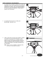
Page 40: ...kit de iluminaci n GG El amplio espacio en el extremo superior de la carcasa del interruptor extra C debe alinearse con el interruptor de reversa de la placa de la carcasa del interruptor J para que c...

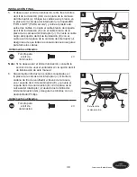
Page 41: ...ici n OFF APAGADO DD J 1 2 La cadena de tiro del centro se utiliza para ENCENDER o APAGAR la luz DD J 2 3 Utilice el interruptor de reversa del ventilador ubicado en la placa de la carcasa del interru...

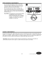
Page 42: ...o hacia la izquierda para que el ventilador funcione Si el interruptor de reversa se configura en la posici n del medio el ventilador no funcionar Fig 3A Fig 3B 3 CUIDADO Y MANTENIMIENTO Al menos dos...

Page 43: ...nillos que sostienen las aspas del ventilador en los brazos de las aspas y en el motor 2 Reemplace la aspa partida 3 No use un regulador de intensidad de rango completo para controlar la velocidad del...

Page 44: ...bles del kit de iluminaci n no est n conectados apropiadamente 3 Una conexi n de los cables no es la correcta 1 Vuelva a instalar las bombillas 2 Aseg rese de que los enchufes macho y hembra del sopor...

Page 45: ...la garant a Debido a las cambiantes condiciones clim ticas esta garant a no cubre cambios en el acabado de lat n incluidos la oxidaci n las picaduras la corrosi n el deslustre o el descascarado Los ac...

Page 46: ...pida piezas tenga a mano el No de modelo o el No de art culo del ventilador disponible PIEZA DESCRIPCI N MODELO 40117 PIEZA MODELO 40118 PIEZA MODELO 40119 PIEZA A Carcasa del motor 0403517 A 0403518...

Reviews: