background image

10

 1. 

1

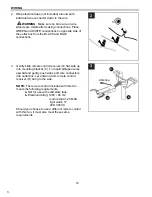
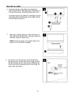
Replace vice (Q) and adjust length of safety cable 
(R), preassembled to motor housing (D), by 
loosening screw and nut on the vice (Q) and pulling 
on the safety cable (R). Adjust slack in safety cable 
(R) to a hand’s length and re-tighten screw and nut 
on vice (Q) securely. The loop at the end of the 
safety cable (R) should just fit over the threads on 
the wood screw (not included). 

Test safety cable (R) by pulling on loose end with 
pliers. If the safety cable (R) slips, then screw and 
nut on vice (Q) must be set tighter.

Q

Screw

Nut

Loop

Wood 
Screw

INSTALLING SAFETY CABLE

2.  Find a secure attachment point (wood ceiling joist  

recommended) and secure safety cable (R) using 
a heavy-duty wood screw, washer and lock 
washer (none included).

NOTE:

 Extra cable slack can be left in ceiling 

area.

R

Wood Screw,

Washer and

Lock Washer

Wood
Joist

2

Loop

R

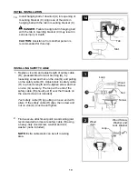
14. Install hanging ball of downrod (A) into opening of 

mounting bracket (C). Align one of the slots in 
hanging ball with the tab in mounting bracket (C). 


DANGER:

 Failure to align slot in hanging ball 

with the tab in mounting bracket (C) may result in 
serious injury or death.

CAUTION:

 Assistance from another person is 

recommended for this step.

C

Tab

14

A

Slot

INITIAL INSTALLATION

Summary of Contents for C-TR56BNK3D1R

Page 1: ...ase Date Questions problems missing parts Before returning to your retailer call our customer service department at 1 800 643 0067 8 a m 6 p m EST Monday Thursday 8 a m 5 p m EST Friday 1 Harbor Breez...

Page 2: ...sure all electrical connections comply with local codes ordinances the Canadian Electrical Code and ANSI NFPA 70 1999 Hire a qualified electrician Make sure the installation site you choose allows a...

Page 3: ...off electricity at main switch or circuit breaker in order to avoid electrical shock NOTE This equipment has been tested and found to comply with the limits for a Class B digital device pursuant to P...

Page 4: ...led G Canopy Mounting Screw 4 preassembled H Motor Screw 6 1 preassembled DESCRIPTION PART QUANTITY DESCRIPTION PART QUANTITY I Lock Washer preassembled 6 1 J Flat Washer preassembled 6 1 K LED Light...

Page 5: ...mated Assembly Time 120 minutes Tools Required for Assembly not included Electrical Tape Phillips Screwdriver Pliers Safety Glasses Stepladder and Wire Strippers Helpful Tools not included AC Tester L...

Page 6: ...cket C Determine mounting method to use A Standard mount B Angle mount Note Flushmount and closemount options are not available for this fan IMPORTANT If using the angle mount ensure the ceiling angle...

Page 7: ...with the angled side of the blade facing down 6 7 7 6 Secure mounting bracket C to outlet box not included using screws spring washers and flat washers provided with the outlet box NOTE It is very im...

Page 8: ...ng D 9a 9b 10 10 Insert downrod A through canopy B and yoke cover E Thread wires and safety cable R from motor housing D up through downrod A B A E D 9b Yoke Set Screw Nut Side view 9a M L A INITIAL I...

Page 9: ...he lead wires and make sure you have pulled them all the way through the top of the downrod Start at the TOP of the hanging ball on the downrod and measure 8 in of lead wire and then cut the excess wi...

Page 10: ...tighter Q Screw Nut Loop Wood Screw INSTALLING SAFETY CABLE 2 Find a secure attachment point wood ceiling joist recommended and secure safety cable R using a heavy duty wood screw washer and lock was...

Page 11: ...CC making sure to screw wire connector CC on in a clockwise direction CAUTION Assistance from another person is recommended for this step Connect all GROUND GREEN wires from fan on downrod A if appli...

Page 12: ...ol receiver O flat side up into mounting bracket C Turn spliced taped wires upward and gently push wires and wire connectors into outlet box Let antenna from remote control receiver O hang to the side...

Page 13: ...opy mounting screws G previously removed Step 4 page 6 and tighten all canopy mounting screws G securely 1 F G B 3 Connect BLUE wire from motor housing D to BLACK wire from LED light kit K Connect WHI...

Page 14: ...s on glass shade U with protrusions on the inside of the light kit fitter Turn glass shade U clockwise until it no longer turns NOTE Pull down gently on the glass shade U to make sure it is secured co...

Page 15: ...ng or household hazardous waste coordinators concerning the specifics of the program in your area You may also locate a recycling center by calling 1 800 8 BATTERY or 1 877 2 RECYCLE or visit www epa...

Page 16: ...ceiling fan Total wattage for this fixture is 17 watts do not attempt to replace the LEDs OPERATING INSTRUCTIONS Operation buttons on the panel of the remote control transmitter 3 button for fan HIGH...

Page 17: ...especially when running the fan at Medium and High speeds Excessive wobbling 1 Blades are loose 2 Unbalanced blades 3 Fan not securely mounted 4 Fan too close to vaulted ceiling 5 Set screw s on motor...

Page 18: ...e warranty Any service performed by an unauthorized person will render the warranty invalid Due to varying climatic conditions this warranty does not cover changes in brass finish rusting pitting tarn...

Reviews: