background image

20

Lowes.com/harborbreeze

TROUBLESHOOTING

PROBLEM

POSSIBLE CAUSE

CORRECTIVE ACTION

The fan is noisy.

1.  The blades are loose.
2.  There is a cracked blade.
3.  The outlet box is not secure.
4.  The mounting bracket is not 

secure.

1. Check and tighten all screws that hold 

the fan blades to the blade arms and the 

motor.

2. Replace the cracked blade.
3. Ensure the outlet box is secured to the 

building structure.

4. Ensure the mounting bracket is secured 

to the outlet box and that the screws are 

tight.

Remote doesn’t 

work.

1. LED indicator does not 

illuminate when remote button 

is pushed.

2. The remote control is not 

synced with the fan’s receiver.

 1.  Replace the remote battery with a new 12-

volt battery. 

 2. Turn off the main power, then turn it back 

on. Within 30 seconds, press and hold 

the high and low speed buttons on the 

remote at the same time for 5 seconds. 

The LED indicator will flash 3 times, 

signaling a successful synchronization. 

Once complete, the fan will start on the 

low speed with the light (if applicable) off.

Summary of Contents for 40821

Page 1: ...s problems missing parts Before returning to your retailer call our customer service department at 1 800 643 0067 8 a m 6 p m EST Monday Thursday 8 a m 5 p m EST Friday Harbor Breeze is a registered t...

Page 2: ...Safety Information 5 Preparation 6 Initial Installation 7 Standard or Angle Mounting Instructions 9 Closemount Instructions 11 Wiring 12 Final Installation 13 Operating Instructions 18 Care and Mainte...

Page 3: ...K Finial Cap preassembled to Light Kit J 1 L Finial preassembled to Light Kit J 1 M Glass Bowl 1 N Blade Arm 5 O Blade 5 P Remote Pack 1 Q Bulb 3 R Blade Balancing Kit 1 S Rubber Washer preassembled...

Page 4: ...4 Lowes com harborbreeze HARDWARE CONTENTS shown actual size Plug Button Qty 1 Wire Connector Qty 1 1 extra AA BB...

Page 5: ...l cause a loud humming noise from the fan To reduce the risk of fire or electric shock do NOT use a full range dimmer switch to control the fan speed WARNING To reduce the risk of fire electric shock...

Page 6: ...able protection against harmful interference in a residential installation This equipment generates uses and can radiate radio frequency energy and if not installed and used in accordance with the ins...

Page 7: ...parately Angle mounting is best suited for angled or vaulted ceilings A longer downrod is sometimes necessary to ensure proper blade clearance Closemount style mounting is more suitable for ceilings l...

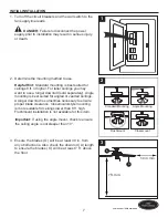
Page 8: ...se the proper hardware when installing the mounting bracket E as this will support the fan Note Do not feed supply wires through the hole in the top of the mounting bracket Important If using the angl...

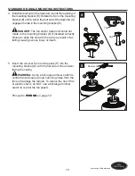
Page 9: ...d pin B and downrod clip C from the downrod A Feed the wire harness from the fan through the downrod A Then insert the downrod A or a longer downrod if required through the canopy D and into the yoke...

Page 10: ...racket E if installed correctly Failure to align the slot with the tab may result in fan falling causing serious injury or death 5 Insert the receiver from remote pack P into the mounting bracket E wi...

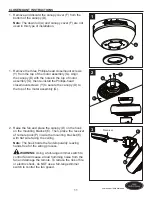
Page 11: ...mount screws Y to secure the canopy D to the top of the motor assembly G 2 Raise the fan and place the canopy D on the hook on the mounting bracket E Then place the receiver of remote pack P inside th...

Page 12: ...r preassembled to the Red wire from the receiver of remote pack P Important The wire harness and the Bare Green ground supply wire will be connected later If supply wires are different colors than ref...

Page 13: ...the wire hooks Wrap the wire harness coming from the downrod A around the wire hooks on the back of the mounting bracket E Important Ensure the wire harness is supported by the wire support to preven...

Page 14: ...opy D avoid pinching wiring or antenna from the receiver of remote pack P between the mounting bracket E and the canopy D 4 Secure the canopy D with the mounting bracket screws W previously removed St...

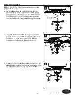
Page 15: ...he single pin connectors from the light kit J blue to black and white to white 7 Align the notch in the switch housing cap I with the reverse switch on the switch housing H Then secure the light kit J...

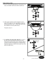
Page 16: ...S and secure with hex nut T Lift the finial cap K onto the threaded rod securing with finial L Proceed to step 13 11 To install the fan without the light kit J remove the hex nut and lock washer from...

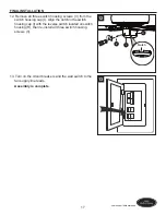
Page 17: ...m the switch housing cap I Align the notch in the switch housing cap I with the reverse switch located on switch housing H then re install all three switch housing screws V 13 Turn on the circuit brea...

Page 18: ...ten the lights CFL Bulbs Turns the lights on and off Note The dimmer function does not work with CFL bulbs 6 D CFL Switch Switch should be set to D to correspond with the included incandescent bulbs w...

Page 19: ...heck the fuse 2 Turn the power off Loosen the canopy and check all connections 3 Check that the connectors from the light kit and fan are connected properly 4 Push the reverse switch completely to the...

Page 20: ...sure the mounting bracket is secured to the outlet box and that the screws are tight Remote doesn t work 1 LED indicator does not illuminate when remote button is pushed 2 The remote control is not sy...

Page 21: ...invalid Due to varying climate conditions this warranty does not cover any changes in plated finishes including rusting pitting corroding tarnishing or peeling Plated metals give their longest useful...

Page 22: ...848 PART A Downrod 0599849 A 0599656 A 0599848 A D Canopy 0599849 B 0599656 B 0599848 B E Mounting Bracket 0599849 C 0599656 C 0599848 C F Canopy Cover 0599849 D 0599656 D 0599848 D K Finial Cap 05998...

Reviews: