background image

49

Lowes.com/harborbreeze

Impreso en China

Harbor Breeze® es una marca registrada de LF, LLC.  

Todos los derechos reservados.

LISTA DE PIEZAS DE REPUESTO

Si busca piezas de repuesto, llame a nuestro Departamento de Servicio al Cliente al 1-800-643-0067, 

de lunes a jueves de 8 a.m. a 6 p.m., y los viernes de 8 a.m. a 5 p.m., hora estándar del Este.

PIEZA #

PIEZA

DESCRIPCIÓN

#0044687

#0043676

#0044622

A

 Varilla

0044687-A

0043676-A

0044622-A

C

 Base

0044687-C

0043676-C

0044622-C

D

 Soporte de montaje

0044687-D

0043676-D

0044622-D

G

 Brazo del aspa

0044687-G

0043676-G

0044622-G

H

 Aspa

0044687-H

0043676-H

0044622-H

 Tazón

0044687-I

0043676-I

0044622-I

K

 Tapa de extremo

0044687-K

0043676-K

0044622-K

L

 Remate

0044687-L

0043676-L

0044622-L

M

 Cubierta de la base

0044687-M

0043676-M

0044622-M

N

 Control remoto

0044687-N

0043676-N

0044622-N

LL

 Paquete de aditamentos

0044687-LL

0043676-LL

0044622-LL

A

H

L

M

C

D

I

G

K

HW

N

Summary of Contents for 40093

Page 1: ...ursday 8 a m 5 p m EST Friday p m EST Monday Friday 1 ATTACH YOUR RECEIPT HERE Serial Number _________________________ Purchase Date _________________________ Lowes com harborbreeze Harbor Breeze is a...

Page 2: ...Safety Information 5 Preparation 6 Initial Installation 7 Standard or Angle Mounting Instructions 9 Closemount Instructions 12 Wiring 13 Final Installation 14 Operating Instructions 19 Care and Mainte...

Page 3: ...embled to the Mounting Bracket D 1 D Mounting Bracket 1 E Light Kit 1 F Motor Assembly 1 G Blade Arm 5 H Blade 5 I Bowl 1 J Bulb 3 K End Cap preassembled to Light Kit E 1 L Finial preassembled to Ligh...

Page 4: ...Pin Qty 1 preassembled to Downrod A Motor Housing Set Screw Qty 2 preassembled to Motor Assembly F Closemount Screw Qty 3 preassembled to Motor Assembly F 1 extra Mounting Bracket Screw Qty 4 preasse...

Page 5: ...a full range dimmer switch to control the fan speed WARNING To reduce the risk of fire electric shock or personal injury mount the fan to an outlet box marked ACCEPTABLE FOR FAN SUPPORT and use the m...

Page 6: ...and can radiate radio frequency energy and if not installed and used in accordance with the instructions may cause harmful interference to radio communications PREPARATION Before beginning the assembl...

Page 7: ...1 2 Determine the mounting method to use Note Flushmount installation is not available for this item Important If using the angle mount check to ensure the ceiling angle is not steeper than 25 2 Downr...

Page 8: ...ling the mounting bracket D as this will support the fan Important If using the angle mount ensure the open end of the mounting bracket D is installed facing the higher point of the ceiling Hardware U...

Page 9: ...ited for ceilings 8 ft or higher For taller ceilings you may want to use a longer downrod not included Angle style mounting is best suited for angled or vaulted ceilings A longer downrod is sometimes...

Page 10: ...Clip x 1 EE Downrod Pin x 1 FF Motor Housing Set Screw x 2 DD FF A F EE 3 4 Depending on the length of downrod you use you may need to cut the lead wires back to simplify the wiring If you decide to...

Page 11: ...ou did not cut back the lead wires in Step 4 Step 5 is not necessary and you may proceed to Step 6 5 6 Install the ball end of the downrod A into the mounting bracket D opening Align the slot in the b...

Page 12: ...r than 8 ft high The downrod A and canopy cover M are not used in this type of installation 1 M C 2 Align the canopy C with the holes in the top of the motor assembly F Secure the canopy C to the top...

Page 13: ...d wire from the mounting bracket D to the Bare Ground supply wire Connect the Red wire from the receiver R to the supply Black wire Connect the Black wire from the receiver R to the Black wire from th...

Page 14: ...ON 1 Remove the two mounting bracket screws HH from the mounting bracket D and loosen the other two screws about 1 4 in Then align the canopy C up to the ceiling over the loose mounting bracket screws...

Page 15: ...on the blade arm G counterclockwise to secure the blade H 3 G H 4 Align the holes of one blade arm G with two holes on the motor assembly F and attach with two motor screws AA previously removed Step...

Page 16: ...the switch housing cap Q Hardware Used II Switch Housing Screw x 3 Nut x 1 5 E KK Q B II 6 Assemble the switch housing cap Q to the rod on top of the light kit E Secure with nut KK Hardware Used Nut...

Page 17: ...on the light kit E IMPORTANT Make sure you allow the bulbs J and lightkit E to cool before you replace the bulbs Note The fan comes with a 190W limiter When the total wattage of the lights is over 19...

Page 18: ...kit E to secure Hardware Used JJ Rubber Washer x 1 KK Nut x 1 I E K L JJ KK 11 12 Attach the pull chain extensions CC or custom pull chains extensions not included to the fan and light pull chains Ass...

Page 19: ...eeling a difference in your comfort Note Wait for the fan to stop before moving the reverse switch 2A In warmer weather push the reverse switch down to display a Sun icon which will result in downward...

Page 20: ...e the switch is pre set to D to correspond with the included incandescent bulbs IMPORTANT The dimmer function does not work with CFL bulbs N O 3 4 To operate the fan using remote control N press and r...

Page 21: ...ff 3 The power is off or the fuse breaker is blown 4 There is a faulty wire connection 1 Firmly push the reverse switch to either the left or right 2 Make sure the wall switch is turned on 3 Turn the...

Page 22: ...until secure The fan operates correctly but the lights are not working if applicable 1 The bulb s not installed correctly 2 The light kit wire plugs are not connected properly 3 There is a faulty wir...

Page 23: ...lid Due to varying climate conditions this warranty does not cover any changes in brass finish including rusting pitting corroding tarnishing or peeling Brass finishes of this type give their longest...

Page 24: ...3676 0044622 A Downrod 0044687 A 0043676 A 0044622 A C Canopy 0044687 C 0043676 C 0044622 C D Mounting Bracket 0044687 D 0043676 D 0044622 D G Blade Arm 0044687 G 0043676 G 0044622 G H Blade 0044687 H...

Page 25: ...volver a la tienda llame a nuestro Departamento de Servicio al Cliente al 1 800 643 0067 de lunes a jueves de 8 a m a 6 p m hora est ndar del Este y los viernes de 8 a m a 5 p m hora est ndar del Est...

Page 26: ...raci n 31 Instalaci n Inicial 32 Instrucciones est ndares y de montaje en ngulo 34 Instrucciones para montaje cerrado 37 Cableado 38 Instalaci n final 39 Instrucciones de funcionamiento 44 Cuidado y m...

Page 27: ...reensamblado en la base C 1 E Kit de iluminaci n 1 F Ensamble del motor 1 G Brazo del aspa 5 H Aspa 5 I Taz n 1 J Bombilla 3 K Tapa de extremo preensamblada en el kit de iluminaci n E 2 L Remate preen...

Page 28: ...ornillo de ajuste de la carcasa del motor Cant 2 preensamblado en el ensamble del motor F Tornillo de montaje cerrado Cant 3 preensamblado en el ensamble del motor F y 1 adicional Tornillo para abraza...

Page 29: ...olar la velocidad del ventilador ADVERTENCIA Para reducir el riesgo de incendios descargas el ctricas o lesiones personales instale el ventilador en una caja de salida marcada como APTA PARA SOSTENER...

Page 30: ...iza y puede irradiar energ a de radiofrecuencia y si no se instala y usa de acuerdo con las instrucciones puede causar interferencia perjudicial a las comunicaciones de radio PREPARACI N Antes de come...

Page 31: ...instalaci n que utilizar Nota La instalaci n de montaje al ras no est disponible para este art culo Importante Si realiza el montaje en ngulo verifique que el ngulo del techo no tenga una inclinaci n...

Page 32: ...que esta sostendr el ventilador Importante Si realiza el montaje en ngulo aseg rese de que el extremo abierto de la abrazadera de montaje D est instalado en direcci n hacia el punto m s alto del techo...

Page 33: ...de 2 44 m de alto o de mayor altura Para techos m s altos se recomienda utilizar una varilla m s larga no incluida El montaje en ngulo es mejor para los techos en ngulo o de b veda En ocasiones es nec...

Page 34: ...Sujetador de la varilla x 1 EE Pasador x 1 FF Tornillo de ajuste de la carcasa del motor x 2 DD FF A F EE 3 4 Dependiendo del largo de la varilla A que utilice es posible que necesite cortar los cabl...

Page 35: ...nductores en el paso 4 el paso 5 no es necesario y puede continuar con el paso 6 en su lugar 5 6 Instale el extremo con la bola de la varilla A en la abertura de la abrazadera de montaje D Alinee la r...

Page 36: ...ola para colgar y la cubierta de la base no se utilizan en este tipo de instalaci n 1 M C 2 Alinee la base C con los orificios de la parte superior del ensamblaje del motor F Fije la base C a la parte...

Page 37: ...erde de conexi n a tierra del ventilador al cable de suministro desnudo de conexi n a tierra Conecte el cable rojo del receptor R al cable de suministro negro Conecte el cable negro del receptor R al...

Page 38: ...s de la abrazadera de montaje HH de la abrazadera de montaje D y afloje los otros dos tornillos aproximadamente 3 18 cm Luego alinee la base C hasta el techo y sobre los tornillos aflojados de la abra...

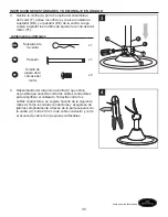
Page 39: ...o a las manecillas del reloj para asegurar el aspa H 3 G H 4 Alinee los orificios de un brazo del aspa G con los dos orificios del ensamble del motor F y f jelos con dos tornillos del motor AA que ret...

Page 40: ...II Tornillo de la carcasa del interruptor x 3 Tuerca x 1 5 E KK Q B II 6 Coloque la tapa de la carcasa del interruptor Q en la varilla en la parte superior del kit de iluminaci n E Fije con una tuerca...

Page 41: ...n E Importante Aseg rese de que las bombillas J y el kit de iluminaci n se enfr en antes de reemplazar las bombillas Nota El ventilador cuenta con un fusible limitador de potencia a 190 vatios Si el v...

Page 42: ...ela de goma x 1 KK Tuerca hexagonal x 1 12 Conecte las extensiones para la cadena de tiro CC o las extensiones para las cadenas de tiro personalizadas no se incluyen con las cadenas de tiro del ventil...

Page 43: ...rencia en su comodidad Nota Espere a que el ventilador se detenga antes de mover el interruptor de reversa 2A En climas m s c lidos presione el interruptor de reversa en la posici n hacia abajo y ver...

Page 44: ...sidad no funciona con bombillas CFL N O 3 4 Funcionamiento del control remoto Para hacer funcionar el ventilador presione y suelte los siguientes botones del control remoto N 1 Ventilador de gran velo...

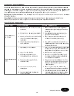
Page 45: ...uemado 4 Una conexi n de los cables no es la correcta 1 Mueva firmemente el interruptor de reversa hacia la izquierda o hacia la derecha 2 Aseg rese de que el interruptor de pared est encendido 3 Enci...

Page 46: ...ras de la caja de salida y no debe moverse 4 Utilice una varilla m s larga o mueva el ventilador a otra ubicaci n 5 Levante la cubierta de horquilla y apriete el tornillo de ajuste en la horquilla ha...

Page 47: ...la garant a Debido a las cambiantes condiciones clim ticas esta garant a no cubre cambios en el acabado de lat n incluidos la oxidaci n las picaduras la corrosi n el deslustre o el descascarado Los ac...

Page 48: ...CRIPCI N 0044687 0043676 0044622 A Varilla 0044687 A 0043676 A 0044622 A C Base 0044687 C 0043676 C 0044622 C D Soporte de montaje 0044687 D 0043676 D 0044622 D G Brazo del aspa 0044687 G 0043676 G 00...

Reviews: