background image

3

PACKAGE CONTENTS

A

B

C

D

E

F

G

PART

DESCRIPTION

QUANTITY

A

Mounting Bracket

1

B

Motor Assembly

1

C

Motor Housing

1

D

Blade Iron

4

E

Blade 

4

F

Glass Shade

1

G

Bulb

1

Package Contents

Summary of Contents for 40016

Page 1: ...Breeze is a registered trademark of LF LLC All Rights Reserved ATTACH YOUR RECEIPT HERE Serial Number Purchase Date Questions problems missing parts Before returning to your retailer call our customer...

Page 2: ...ntents 4 Safety Information 5 Preparation 6 Assembly Instructions 7 Wiring 10 Final Installation 12 Light Kit Installation 13 Operating Instructions 14 Care And Maintenance 15 Troubleshooting 15 Limit...

Page 3: ...3 PACKAGE CONTENTS A B C D E F G PART DESCRIPTION QUANTITY A Mounting Bracket 1 B Motor Assembly 1 C Motor Housing 1 D Blade Iron 4 E Blade 4 F Glass Shade 1 G Bulb 1...

Page 4: ...CC DD FF GG EE PART DESCRIPTION QUANTITY AA Blade Iron Screws 12 1 Extra BB Blade Washer 12 1 Extra CC Short Mounting Screw preasssembled 3 DD Pull Chain Extension 2 EE Wire Connector 4 FF Blade Isola...

Page 5: ...hock do NOT use a full range dimmer switch to control DANGER When using an existing outlet box make sure the outlet box is securely attached to the building structure and can support the full weight o...

Page 6: ...re wire is present After opening top of carton remove mounting hardware package from foam inserts Remove motor from packing and place on carpet or on foam to avoid damage to finish 2 CAUTION Carefully...

Page 7: ...mounted to the ceiling downrod mount and angle mount is not available for this fan 3 Check to make sure blades E will be at least 30 in from any obstructions Check and ensure blades E are at least 7 f...

Page 8: ...ounting bracket A as this will support the fan Note Remove the preassembled short mounting screws CC from the mounting bracket A and motor assembly B before continuing to the next step 5 Carefully han...

Page 9: ...C Then turn the housing clockwise so the screws move toward the end of the L slots The housing should now sit securely on the screws preassembled on the mounting bracket A 8 7 There are 4 housing moun...

Page 10: ...that fits your situation and make appropriate wiring connections as follows NOTE For each wire connection below and on the following page use one of the wire connectors EE making sure to screw wire c...

Page 11: ...AN AND LIGHT CONTROLLED BY TWO WALL SWITCHES If you intend to control the fan and light with separate wall switches connect BLACK wire from fan to BLACK wire from the independent wall switch for the f...

Page 12: ...assembly to the motor by inserting the alignment post into the slot on the bottom of the motor and tightening the motor screws GG Please note the motor screws may be preassembled to the motor Note Ma...

Page 13: ...nsert the glass shade F into the fixture Tighten preassembled glass mounting screws manually until finger tight Do not overtighten Note Loosen the thumbscrews before inserting the globe then retighten...

Page 14: ...ter without feeling a difference in your comfort Note Wait for fan to stop before moving the reverse switch 2A In warmer weather push the reverse switch to UP and see a Sun icon which will result in d...

Page 15: ...hours continuously on medium or high speed for break in period 5 Make sure the outlet box is secured to building structure 6 Make sure the mounting bracket is secured to the outlet box screws are tig...

Page 16: ...n or by affixing any accessories is not covered by this warranty The manufacturer assumes no responsibility whatsoever for fan installation during the limited lifetime warranty Any service performed b...

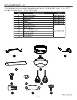
Page 17: ...m EST Friday Printed in China A C D E F AA BB EE FF DD GG PART DESCRIPTION PART A Mounting Bracket 4L0000000024 C Motor Housing 4L0000000025 D Blade Iron 4L0000000026 E Blade 4L0000000027 F Glass Sha...

Reviews: