background image

ASSEMBLY INSTRUCTIONS

10

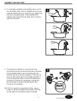
10. Attach blade brackets (I) to blades (K) with screws 

(M) and metal or fiber washers (L). Do not tighten 
screws (M) until each screw (M) has been started. 
Then, tighten each screw (M) starting with the center 
screw. 


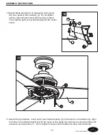
11. Assembling the blades:  Insert end of each blade bracket (I) into the slots on the blade ring. Align 

the holes on the blade bracket (I) with the holes on the blade ring and secure using the blade iron 
screws w/ semi-washers (Y).  Do not tighten screws until all blades (K) have been attached.


11

10

K

L

K

L

K

L

K

L

M

M

M

E

E

E

I

K

K

K

K

Y

E

E

E

I

Lowes.com/harborbreeze

Summary of Contents for 35062

Page 1: ...an ais p 15 Questions problems missing parts Before returning to your retailer call our customer service department at 1 800 643 0067 8 a m 6 p m EST Monday Thursday 8 a m 5 p m EST Friday ATTACH YOUR...

Page 2: ...PACKAGE CONTENTS 2 Q E E E E G M B C D R H L Q Q W Q CC Q P BB Z AA E E E E E E E E E E E K E E E I Y A G G O M B C U D D F R R X R S R V H L Lowes com harborbreeze J T T J J N...

Page 3: ...ly 1 Blades 3 Blade Washers 9 Blade Screws 9 Shipping Retainers 3 Motor Coupling Cover 1 Switch Housing 1 Receiver 1 Remote 1 Switch Cover 1 Set Screws 2 Shoulder Screws 2 Glass Shade 1 Bulb 1 Housing...

Page 4: ...allows a minimum of 7 feet from the floor to the end of the blades PREPARATION Before beginning assembly of product make sure all parts are present Compare parts with package contents list and diagra...

Page 5: ...t box Important If attaching the fan to a sloped ceiling make sure open end of mounting bracket is installed facing the roof Do not install fan on a ceiling with a pitch greater than 20 1 A B C 2 Chec...

Page 6: ...od D Insert the downrod into motor assembly J Secure clevis pin F with hairpin E clip and tighten setscrews T 3 E E E U E E E A E E E U E E U E E E U E E E D 4 Loosen the two shoulder screws U without...

Page 7: ...n s dip switch settings in the transmitter and remote to a new pattern NOTE If not using for long periods of time remove battery to prevent damage to transmitter Store the remote away from excessive h...

Page 8: ...otor wire to BLUE receiver unit wire marked FOR LIGHT Connect BLACK fan motor wire to BLACK receiver unit wire marked TO MOTOR L Connect BLACK supply wire to RED receiver unit wire marked AC IN L Conn...

Page 9: ...nd green wires to one side of the box and the black wire toward the other side 9 Loosen the two shoulder screws U without fully removing the hanger bracket A Assemble canopy G by rotating keyhole slot...

Page 10: ...M starting with the center screw 11 Assembling the blades Insert end of each blade bracket I into the slots on the blade ring Align the holes on the blade bracket I with the holes on the blade ring an...

Page 11: ...align decorative tubes prior to tightening the screws 13 Securely attach the switch cover S connectors to the wire harness switch housing BLACK to BLACK WHITE to WHITE Remove one of the three screws X...

Page 12: ...s inside switch cover with the cutouts on the glass Turn clockwise to lock in plate and don t over tighten or force it NOTE Do not replace bulb when hot 16 Install remote R holder onto wall with screw...

Page 13: ...uickly to turn light on or off For DIMMER function press and hold button to dim the light The light will cycle from bright to dim to bright until button is released Light will maintain last setting if...

Page 14: ...tarnishing corroding or peeling Brass finish fans maintain their beauty when protected from varying weather conditions Any glass provided with this fan is not covered by the warranty Any replacement o...

Page 15: ...ons des probl mes des pi ces manquantes Avant de retourner l article au d taillant appelez notre service la client le au 1 800 643 0067 entre 8 h et 18 h HNE du lundi au jeudi ou entre 8 h et 17 h HNE...

Page 16: ...CONTENU DE L EMBALLAGE 16 Q E E E E G M B C D H L Q Q W Q P E E E E E E E E E E E K E E E I Y A G G O M B C U D D F R X R S R V H L Lowes com harborbreeze J T T J J N R R BB Z AA Q CC...

Page 17: ...es de pale 9 Vis de pale 9 Attaches d exp dition 3 Couvercle d accouplement du moteur 1 Bo tier d interrupteur 1 R cepteur 1 Contr le distance 1 Couvercle d interrupteur 1 Vis de serrage 2 Vis pauleme...

Page 18: ...r l extr mit des pales PR PARATION Avant de commencer l assemblage du produit assurez vous d avoir toutes les pi ces Comparez les pi ces dans l emballage avec la liste et le tableau ci dessus S il y a...

Page 19: ...installez le ventilateur un plafond en pente assurez vous que l extr mit ouverte de la fixation de montage soit install e face au toit N installez pas le ventilateur sur un plafond avec une inclinais...

Page 20: ...oteur J alignant les trous dans le support de la tige de descente D avec les trous de la tige de descente D Fixez l axe paulement F avec la pince d pingle cheveux E et resserrez les vis de serrage T 3...

Page 21: ...tteur et le contr le distance un nouveau motif REMARQUE Si vous ne l utilisez pas pendant de longues p riodes retirez la pile pour viter les dommages au transmetteur Rangez le contr le distance loin d...

Page 22: ...U portant la mention FOR LIGHT POUR L CLAIRAGE Branchez le fil du moteur du ventilateur NOIR au fil du r cepteur NOIR portant la mention TO MOTOR N AU MOTEUR N Branchez le fil d alimentation NOIR au f...

Page 23: ...rts d un c t du coffret et le fil noir vers l autre c t 9 Desserrez les deux vis paulement U sans retirer compl tement de la fixation suspendue A Assemblez le couvercle en tournant la fente du trou de...

Page 24: ...commen ant avec la vis centrale 11 Assembler les pales ins rez l extr mit de chaque fixation de pale I dans les fentes de l anneau des pales Alignez les trous de la fixation de pale I avec les trous s...

Page 25: ...n cessaire pour aligner les tubes d coratifs avant de resserrer les vis 13 Fixez bien les connecteurs du couvercle d interrupteur S au bo tier d interrupteur de faisceau de fils NOIR NOIR BLANC BLANC...

Page 26: ...r avec les d coupes sur le verre Tournez dans le sens horaire pour verrouiller dans la plaque et ne resserrez pas trop ni ne forcez REMARQUE Ne replacez pas l ampoule lorsque c est chaud 16 Installez...

Page 27: ...re Pour la fonction de GRADATEUR enfoncez et gardez le bouton enfonc pour r duire l intensit de la lumi re L clairage cyclera de lumineux faible lumineux jusqu ce que le bouton soit d gag La lumi re c...

Page 28: ...corrosion ou l caillage Les ventilateurs au fini de laiton conservent leur beaut lorsqu ils sont prot g s des conditions climatiques vari es Tout verre fourni avec ce ventilateur n est pas couvert par...

Reviews: