background image

6

7

ASSEMBLY INSTRUCTIONS

ASSEMBLY INSTRUCTIONS

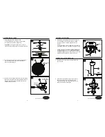
 1.  Determine mounting method to use.

      A - Downrod Mount (normal or angled ceiling)

      B - Closemount (normal ceiling only)

      Important:

 lf using the angle mount, check to

      make sure the ceiling angle is not steeper than 20°.

4.  Install the mounting bracket (A) to the outlet box 

(not included) using the two screws provided 

with the outlet box. Securely tighten the two 

screws.

2.  Remove and discard the five rubber inserts and

      five mounting screws from the underside of 

      the motor assembly (F).

2.  Insert downrod assembly (E) through canopy 

(B), canopy cover (C) and yoke cover (D). 

Thread wires from the motor assembly (F) up 

through downrod assembly (E).


Outlet box

A

4

3.  Remove the mounting bracket (A) from the canopy 

(B) by loosening the four preassembled screws on 

the top of the canopy (B). Remove the two non-

slotted screws and save.

1

A

B


Loosen but

do not remove

A

Remove

and save

A

B

3

If using the angle mount, make sure open end of 

mounting bracket (A) is installed facing the ceiling.

Follow mounting instructions for 

Downrod Style 

Fan Mounting

 on page 7 or 

Closemount Style 

Fan Mounting

 on page 8, depending on mounting 

method (A or B) chosen in step 1 on page 6.

DOWNROD STYLE FAN MOUNTING

1.  Remove pin and clip from downrod assembly 

(E) and save.

Rubber insert 

and screw

F

2

E

B

C

D

E

Clip

Pin

E

1

2

Lowes.com/harborbreeze

Lowes.com/harborbreeze

Summary of Contents for 00887

Page 1: ...a registered trademark of LF LLC All Rights Reserved Questions problems missing parts Before returning to your retailer call our customer service department at 1 866 473 4537 8 a m 7 p m EST Monday F...

Page 2: ...RIC SHOCK HAZARD To reduce the risk of electric shock do not use this fan with any solid state speed control device ELECTRIC SHOCK HAZARD To reduce the risk of electric shock make sure the electricity...

Page 3: ...strippers Helpful Tools not included Electrical circuit tester PACKAGE CONTENTS A Mounting Bracket preassembled to canopy B Canopy Canopy Cover preassembled to canopy B Yoke Cover Downrod Assembly Mo...

Page 4: ...nd yoke cover D Thread wires from the motor assembly F up through downrod assembly E Outlet box A 4 3 Remove the mounting bracket A from the canopy B by loosening the four preassembled screws on the t...

Page 5: ...e the rubber gasket FF over the remaining screws on motor assembly F Pull wires from motor assembly F through hole in canopy B and attach canopy B using the three screws previously removed Tighten the...

Page 6: ...tach blade H to a blade bracket G using three blade screws BB Repeat for remaining blade assemblies 11 2 Re install the two screws that were previously removed step 3 page 6 to fully secure the canopy...

Page 7: ...n glass K Make sure pull chain hangs clear and is not tangled in light kit J Thread light kit pull chain through center hole on glass K Place previously removed rubber washer and hex nut onto the pipe...

Page 8: ...switch between clockwise and counterclockwise rotations flip the fan reversal switch WARNING Wait for fan to stop before reversing the switch A In cooler weather clockwise rotation creates an upward...

Page 9: ...e or at our option replace the ceiling fan with a comparable or superior model To obtain warranty service present a copy of your sales receipt as proof of purchase All cost of removal and reinstallati...

Reviews: