background image

English _

17


!

USE AUDIO SER

VER

Output Device

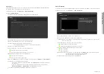
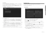
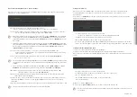
The speakers registered as the <Zone> of the area for broadcasting will be displayed in the Output Device 
list. <

Zone

> refers to one speaker set as an output device.

1. 

On the Home screen, click 

<Operate>


;


<Device Monitoring>

.

2. 

Click the 

<Output Device>

.


~

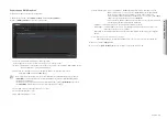
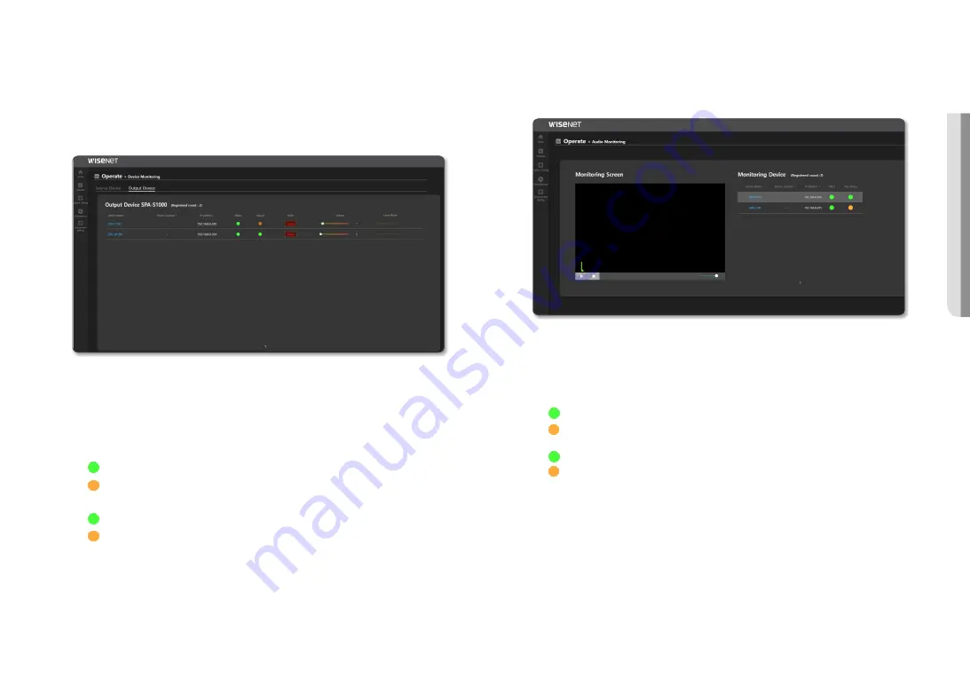
The number of devices registered as the Output Device will be displayed.


~

Device Name: Displays the name of the output device name.


~

Device Location: Displays the location of the output device.


~

IP address:  Displays the IP address of the output device. 

If you click the IP address, you can go to the website of the device.


~

Channel :  The channel will be displayed.


~

Status: Displays the connection status of the output device.


-

: When the device is connected normally


-

: When there is interference with the device connection


~

Output: Displays the play status of the output device.


-

: When the device plays audio


-

: When the device does not play audio


~

Mute: If the [

Mute

] button is turned on, the audio source will not play in <

Operate

;

 <

Button Mode

>.


~

Volume:  Move a control bar to adjust the volume. 

If the volume is adjusted, the speaker volume of the <

Button mode

> property is reflected on 

the same level.  
When the volume is adjusted, its output volume will be reflected at the same level in the 
<

Operation Settings

;

 <

DSP Setting

> of the Output Device speaker.


~

Level Meter: A signal value being played is indicated as a level meter.

Audio Monitoring

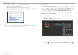
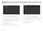
You can monitor the status of the Output Device speakers registered in the <

Zone

> of the area to broadcast. 

1. 

On the Home screen, click <

Operate

;

 <

Audio Monitoring

>.


~

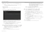
Device Name: Displays the name of the output device.


~

Device Location: Displays the location of the output device.


~

IP address:  Displays the IP address of the output device. If you click the IP address, you can go to the 

website of the device.


~

Status: Displays the connection status of the output device.


-

: When the device is connected normally


-

: When there is interference with the device connection


~

Play Status: Displays the amp output status of the speaker. 


-

: Amp output is On


-

: Amp output is Off


~

Monitoring Screen:   Select a device to monitor and press the [

Play

 (

+

)] button, then the audio signals 

detected by the device microphone will be visualized.  
You cannot hear the actual output audio source.


~

Volume Control: The monitoring volume can be adjusted.

Summary of Contents for SPA-S1000

Page 1: ...IP AUDIO SERVER User Manual SPA S1000...

Page 2: ...n this document but no formal guarantee shall be provided Use of this document and the subsequent results shall be entirely on the user s own responsibility Hanwha Vision reserves the right to change...

Page 3: ...mation point within an equilateral triangle is intended to alert the user to the presence of important operating and maintenance servicing instructions in the literature accompanying the product CAUTI...

Page 4: ...e it is exposed to direct sunlight near heating equipment or heavy cold area 22 Do not place this apparatus near conductive material 23 Do not attempt to service this apparatus yourself 24 Do not plac...

Page 5: ...stem Configuration Diagram 7 Connecting To Power And A Network STARTING 8 8 Connecting to a PC 8 Access Product 11 Logging In ENVIRONMENT SETTINGS 12 12 System Management 14 Network Settings 15 Time S...

Page 6: ...status LED Indicates power connection f AC Power code connection terminal Provides AC Power Name Function Description g Power switch Power on off switch h Power input terminal DC 24 V DC Power input t...

Page 7: ...registered proper broadcasting cannot be performed The IP audio module can be used as an IP speaker when connected to an analog speaker with a permissible input of 10W or higher and an impedance of 8...

Page 8: ...sswords Use Device Manager to set the initial password and IP address to use Registering using Device Manager If the product is connected to a network which includes a computer where the device manage...

Page 9: ...are not used in the network audio product 4 Products with IP addresses must be logged in from the Credential menu to be queried as Login OK When you execute New Project Search authentication is cancel...

Page 10: ...l IP address into the web browser s address bar 2 The admin account password must be registered when accessing the product for the first time When the Change Password window appears please enter a new...

Page 11: ...menu of the web page Do not disconnect the power until the system initialization is complete after pressing the RESET button of the product or during product resetting 10 M To change the network setti...

Page 12: ...Setting System Management 2 By clicking Destination Account from Password Change select the account you want to change and set the password 3 Click the Apply button after entering a new password in th...

Page 13: ...ck Environment Setting System Management 2 Click Reset after checking the locked account on Account lock status The lock icon is changed to unlocked and the number of retries for the account is reset...

Page 14: ...and you must register if you wish to use the product As the log information will be deleted when the product s system is initialized please download it in advance NETWORK SETTINGS You can change the n...

Page 15: ...ime server 2 Click Apply to apply the set Time and Date information J If the product is used in a local network environment without an external Internet connection the time information may become inco...

Page 16: ...bsite Korean English supported g Go to the Official Website If you click Hanwha the screen will move to the Hanwha Vision Official Website M The optimal monitor resolution is 1920x1080 OPERATION MODE...

Page 17: ...volume If the volume is adjusted the speaker volume of the Button mode property is reflected on the same level When the volume is adjusted its output volume will be reflected at the same level in the...

Page 18: ...f the source device to Multicast and broadcast the BGM sound source of the source device to the output device the Multicast IP address and the port information of the source device will be sent to the...

Page 19: ...an select an output group among the set groups and duplicate selection is also possible The selected group will be displayed as highlighted When you select the Source Device and group and click the St...

Page 20: ...reconfigure it The zone device which can be broadcast is displayed as Broadcasting count Total count If you manually control the speakers in Speaker Mode while running all the broadcasts with the Cont...

Page 21: ...register all the other speakers as Speaker mode Control Mode When you run Start Broadcasting Stop Broadcasting from the Operate Button Mode you can control the zone devices with either the TCP or UDP...

Page 22: ...irectly uploaded on PC you can select one from the Icon list 3 Once set click the Apply button 4 If you click the View Settings button the set value can be saved as a CSV file M You can use the Contro...

Page 23: ...de broadcast will be kept since the priority of the microphone is higher Source Name Inputs or changes the name of a source Source Type Displayed as mic CH Name Displayed as 1 mic Transmission Method...

Page 24: ...el Displayed as audio_output_1 2 Once set click the Apply button 3 If you click the View Settings button the set value can be saved as a CSV file M As the same speakers can be registered more than onc...

Page 25: ...oadcast as per the scenario set in the All Event Preset List if an event such as the Event Preset of the button mode RM button of the microphone device or an external signal CP of the audio module occ...

Page 26: ...e Output setting the Contact Closure Output signal will be active until the Contact Closure INPUT is Off If Contact Closure INPUT is Off while a sound source is being broadcasted the sound source will...

Page 27: ...lume can be set Initial value 50 input value 0 100 The output volume is reflected only to Event Preset Delay Enter the delayed time before starting scenario broadcasting once the event has taken place...

Page 28: ...schedules the holiday schedule will not be reflected even if you upload a downloaded file For holiday schedules use the download and upload functions of the Holiday menu Copy Schedules for each month...

Page 29: ...pecific day the schedule is set on the specific date for every month or year If you specify a date range in Month or Year and select days of the week in Everyday the schedule is set only for those day...

Page 30: ...t has an event priority set as 2000 in the Event Preset if the schedule time for a schedule that has a priority set as 1000 in the Annual Scheduler comes up the Event Preset broadcast will stop and th...

Page 31: ...when the product s system is initialized please download it in advance M Every input field must be filled in Special characters cannot be input in the input field Locate a mouse pointer on a failure...

Page 32: ...f where and how they can take these items for environmentally safe recycling Business users should contact their supplier and check the terms and conditions of the purchase contract This product and i...

Page 33: ......
Reviews: