background image


Multimeter 

DSO8000E Series HandHeld Oscilloscope User Manual                                                                                                66 


Figure 7-9 DC Current Measurement for 10A 

Making an AC Current Measurement 

To measure an AC current which is less than 600 mA, do the following: 

1) Press the F1 key to select A and then DC appears on the screen. The unit on the main reading 
screen is mA,and mA will display on the bottom of the screen, press F2 to switch the measurement 
between mA and 10A. 600mA is acquiescently. 

2) Press the F2 key once and AC will display on the bottom of the screen. 

3) Insert the black lead into the COM banana jack input and the red lead into the mA banana jack   

input. 

4) Connect the red and black leads to the measured points and the AC current value of measured   

points will be displayed on the screen. 

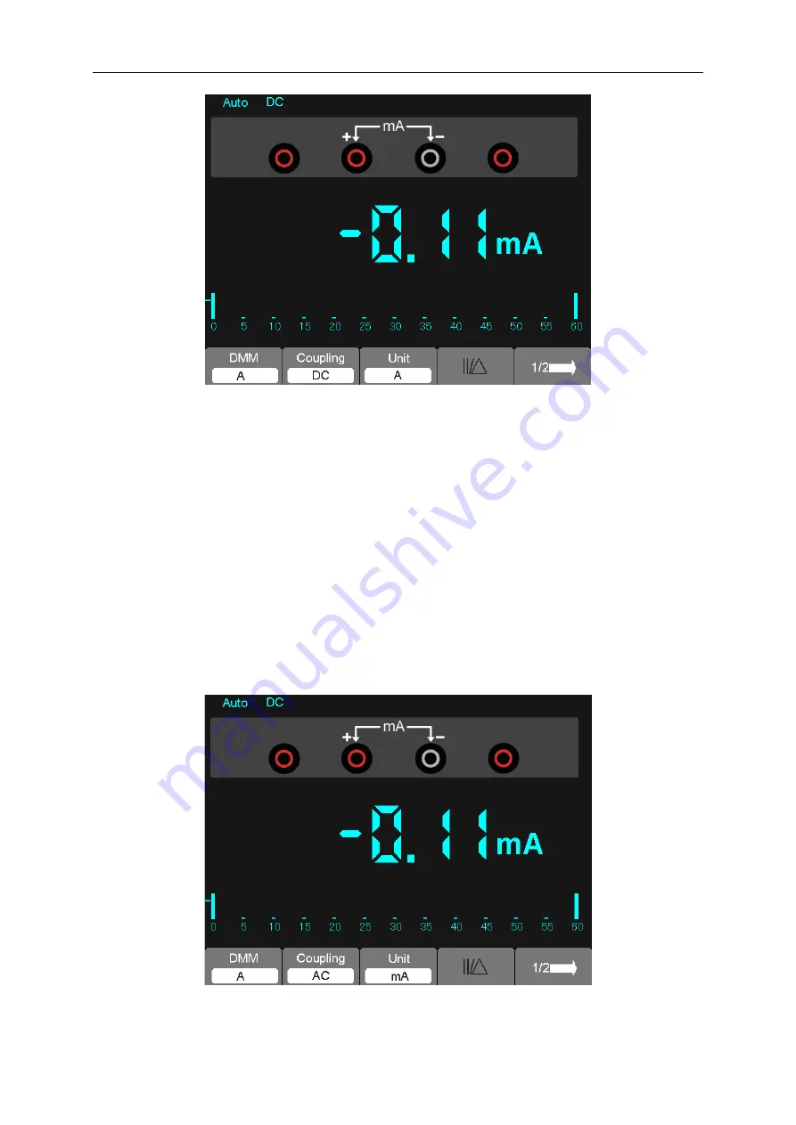
Then, the screen will look like the following figure 7-10. 


Figure 7-10 AC Current Measurement for 600 mA 

Summary of Contents for DSO8000E Series

Page 1: ... V1 0 3 DSO8000E SERIES HANDHELD OSCILLOSCOPE 8072E 8102E 8152E 8202E USER S MANUAL ...

Page 2: ...oscope 4 3 2 2 Connect the oscilloscope 4 3 2 3 Observe the waveform 5 3 3 Probe Examination 5 3 3 1 Safety 5 3 3 2 Use of Probe Check Wizard 6 3 4 Manual Probe Compensation 6 3 5 Probe Attenuation Setting 7 3 6 Self Calibration 7 Chapter 4 Main Feature Description 8 4 1 Oscilloscope Setup 8 4 2 Trigger 8 4 3 Data Acquisition 9 4 4 Waveform Scaling and Positioning 10 4 5 Waveform Measurement 11 Ch...

Page 3: ... Slope Trigger to Capture Particular Slope Signal 52 6 9 Example 9 Using Overtime Trigger to Measure Long Pulse Signal 53 6 10 Example 10 Using Math Functions to Analyze Waveforms 54 6 11 Example 11 Measuring Data Propagation Delay 55 6 12 Example 12 Back light control 56 6 13 Example 13 Auto shut down 57 6 14 Example 14 Setting Net IP 57 6 15 Example 15 Charging 58 Chapter 7 Multimeter 60 Chapter...

Page 4: ...Contents DSO8000E Series HandHeld Oscilloscope User Manual iii Chapter 13 Services and Support 89 Appendix A Harmful and Poisonous Substances or Elements 90 ...

Page 5: ... Co Ltd hereinafter referred to as Hantek Hantek reserves all rights to modify this document without prior notice Please contact Hantek for the latest version of this document before placing an order Hantek has made every effort to ensure the accuracy of this document but does not guarantee the absence of errors Moreover Hantek assumes no responsibility in obtaining permission and authorization of...

Page 6: ...To avoid fire or shock hazard check all ratings and markings on the product Refer to the product manual for detailed information about ratings before making connections to the product Do not operate without covers Do not operate this product with covers or panels removed Avoid exposed circuitry Do not touch exposed connections and components when power is present Do not operate with suspected fail...

Page 7: ...roduct 1 5 Product Scrapping Device Recycling We need extract and utilize natural resources to produce this device If you do not reclaim the device in a proper way some substances it contains may become harmful or poisonous to environments or human bodies To avoid them being released outside and to minimize the waste of natural resources we suggest you reasonably call back this device to ensure pr...

Page 8: ...tcut keys help you save a lot of time in operation the Autoset function lets you detect sine and square waves automatically the Probe Check Wizard guides you to adjust the probe compensation and set the Probe option attenuation factor By using these the methods the oscilloscope provides context sensitive hyperlinks and an index you may master all operations on the device in quite a short time so a...

Page 9: ...to your oscilloscope 3 2 1 Power on the oscilloscope Press the ON OFF button The default Probe option attenuation setting is 10X The default probe parameter 3 2 2 Connect the oscilloscope Set the switch on the probe to 1X and connect the probe to Channel 1 on the oscilloscope First align the slot in the probe connector with the protuberance on the CH1 BNC and push to connect then turn to right to ...

Page 10: ...NU button and remove Channel 1 Push the CH2 MENU button and repeat Step 2 and Step 3 to observe Channel 2 3 3 Probe Examination 3 3 1 Safety When using the probe keep your fingers behind the guard on the probe body to avoid electric shock Do not touch metallic portions of the probe head while it is connected to a voltage source Connect the probe to the oscilloscope and connect the ground terminal ...

Page 11: ...h the probe to the input channel Uncompensated or miscompensated probes may lead to errors or faults in measurement To adjust the probe compensation follow the steps below 1 Set the Probe option attenuation in the channel menu to 10X Set the switch on the probe to 10X and connect the probe to Channel 1 on the oscilloscope If you use the probe hook tip ensure it is firmly inserted onto the probe At...

Page 12: ...illoscope Switch settings are 1X and 10X When the Attenuation switch is set to 1X the probe limits the bandwidth of the oscilloscope to 6MHz To use the full bandwidth of the oscilloscope be sure to set the switch to 10X 3 6 Self Calibration The self calibration routine helps optimize the oscilloscope signal path for maximum measurement accuracy You can run the routine at any time but should always...

Page 13: ... convert unstable displays or blank screens to meaningful waveforms Here introduce some basic concepts about trigger Trigger Source The trigger can be generated with multiple sources The most common one is the input channel alternative between CH1 and CH2 Whether the input signal is displayed or not it can trigger normal operations Trigger Type The oscilloscope has six types of triggers Edge Video...

Page 14: ...Coupling option Trigger Position The horizontal position control establishes the time between the trigger position and the screen center Slope and Level The Slope and Level controls help to define the trigger The Slope option determines whether the trigger point is on the rising or falling edge of a signal To perform the trigger slope control press the TRIG MENU button select an Edge trigger and u...

Page 15: ...cale and position Once the scale changes the waveform display will increase or decrease in size Once the position changes the waveform will move up down right or left The channel reference indicator located on the left of the graticule identifies each waveform on the screen It points to the ground level of the waveform record Vertical Scale and Position The vertical position of a waveform can be c...

Page 16: ...late your peak to peak voltage as follows 6 divisions x 50mV division 300mV Cursor This method allows you to take measurements by moving the cursors Cursors always appear in pairs and the displayed readouts are just their measured values There are two kinds of cursors Amplitude Cursor and Time Cursor The amplitude cursor appear as a horizontal broken line measuring the vertical parameters The time...

Page 17: ... we will give a quick overview of all control buttons on the front panel as well as the displayed information on the screen and relative testing operations The figure below illustrates the front panel of the DSO8000E series digital oscilloscope Front Panel of DSO8000E Series Description 1 LCD Display 2 F1 F5 Sets or switch options for the menu 3 Power light 4 MEAS Shows Measurement menu ...

Page 18: ... Horizontal menu 16 VERTICAL Adjust the signal vertical position 17 VOLTS Decrease or Increase the voltage div 18 Power key 19 REF Shows the REF menu 20 MATH Shows the Math or REF menu 21 CH2 Shows the CH2 menu 22 CH1 Shows the CH1 menu 23 UTILITY Shows Utility menu 24 SAVE RECALL Shows SAVE or RECALL menu 25 RECORDER 26 SCOPE DMM Switch DMM Scope function or Waveform Generator function interface ...

Page 19: ...acquiring waveforms in the absence of triggers The oscilloscope is acquiring and displaying waveform data continuously in scan mode The oscilloscope has stopped acquiring waveform data S The oscilloscope has finished a single sequence acquisition 5 Tool Icon If this icon lights up it means the keyboard of the oscilloscope is locked by the host computer via USB control If this icon lights up it mea...

Page 20: ...ase differences such as those represented by Lissajous patterns The format plots the voltage on CH1 against the voltage on CH2 where CH1 is the horizontal axis and CH2 is the vertical axis The oscilloscope uses the untriggered Normal acquisition mode and displays data as dots The sampling rate is fixed at 1 MS s The oscilloscope can acquire waveforms in YT format at any sampling rate You may view ...

Page 21: ...trl Double Win Single Win Set the Current window mode to single or double window Window Sel Major Win Minor Win Selects the major or minor window in dual window mode The window is highlighted once selected Press this option button in single window mode to enter the daul window mode HoldOff Select this menu and click the up and down Arrow keys to adjust the trigger holdoff time within the range of ...

Page 22: ...sed to change the horizontal time scale so as to magnify or compress the waveform horizontally If the waveform acquisition is stopped by using the RUN STOP button the TIME DIV control will expand or compress the waveform In dual window mode push button F1 to select major or minor window When the major window is selected the F1 button provides the same functions as it provides in single mode window...

Page 23: ...channels correspond to two bars 2 Menu CH1 CH2 Display vertical menu options turn on or off the display of channel waveforms Options Settings Comments Coupling DC AC GND DC passes both DC and AC components of the input signal AC blocks the DC component of the input signal and attenuates signals below 10Hz Ground disconnects the input signal 20MHz Bandwidth Limit Unlimited Limited Limits the bandwi...

Page 24: ...waveform The vertical size of the display on the screen will change increase or decrease to the ground level Also you may use the key F3 to switch between coarse and fine 4 MATH MENU Display the waveform math operations See the table below for details The MATH menu contains source options for all math operations Operations Source Options Comments CH1 CH2 Add Channel 1 to Channel 2 CH1 CH2 Subtract...

Page 25: ...in YT waveform before using the FFT mode Follow the steps below 1 Push the AUTO button to display a YT waveform 2 Click the Vertical Position key to vertically move the YT waveform to the center zero division so as to ensure the FFT will display a true DC value 3 Click the Horizontal Position key to position the part of the YT waveform to be analyzed in the center eight divisions of the screen The...

Page 26: ...the FFT Zoom function to expand the FFT spectrum so that you can clearly view the frequency components at each of the 1024 data points in the FFT spectrum Note The oscilloscope s vertical response is a little bit larger than its bandwidth 70MHz 100MHz 150MHz or 200MHz depending on the model or 20MHz when the Bandwidth Limit option is set to Limited Therefore the FFT spectrum can display valid freq...

Page 27: ... leakage in the FFT spectrum The FFT algorithm assumes that the YT waveform repeats all the time When the number of cycles is integral 1 2 3 the YT waveform starts and ends at the same amplitude and there are no discontinuities in the signal shape If the number of cycles is nonintegral the YT waveform starts and ends at different amplitudes and transitions between the start and end points will cau...

Page 28: ...lution and amplitude accuracy for each type of window You shall determine which one to choose according to the object you want to measure and the source signal characteristics Window Measurement Characteristics Hanning Periodic Waveform Better frequency poorer amplitude accuracy than Flattop Flattop Periodic Waveform Better amplitude poorer frequency accuracy than Hanning Rectangular Pulse or Tran...

Page 29: ...erve the frequency components above 20MHz set the Bandwidth Limit option to Limited Filter the signal input from outside and limit the bandwidth of the source waveform to lower than the Nyquist frequency Identify and ignore the aliased frequencies Use zoom controls and cursors to magnify and measure the FFT spectrum 5 3 1 6 Magnifying and Positioning FFT Spectrum You may scale the FFT spectrum and...

Page 30: ...rsors to measure at any zoom factor Push the CURSOR button choose the Source option and then select Math Press the Type option button to select between Amplitude and Frequency Click the SELECT CURSOR option to choose a cursor Then move Cursor S and Cursor E Use the horizontal cursor to measure the amplitude and the vertical cursor to measure the frequency Now the display at the DELTA menu is just ...

Page 31: ... amount of time based on the TIME DIV setting The oscilloscope goes into the scan mode at 80ms div or slower time base settings In the Normal mode the oscilloscope updates the display only when it detects a valid trigger condition New waveforms are not displayed until they replace old ones Use this mode to just view valid triggered waveforms Only after the first trigger does the display appear Cou...

Page 32: ...er always occurs on negative going sync pulses If the video signal contains positive going sync pulses use the Inverted Polarity option Pulse Width Trigger You can use it to trigger on aberrant pulses Options Settings Comments Pulse With Pulse highlighted the trigger occurs on pulses that meet the trigger condition defined by the Source When and Set Pulse Width options Source CH1 CH2 EXT 5 Select ...

Page 33: ... Select the slope type of signal Mode Auto Normal Select the type of trigger The Normal mode is best for most pulse width trigger applications Coupling AC DC Noise Reject HF Reject LF Reject Selects the components of the trigger signal applied to the trigger circuitry Vertical V1 V2 Adjust the vertical window by setting two trigger levels Select this option and press F3 to choose V1 or V2 When Sel...

Page 34: ... CH2 to select different trigger modes and to display waveforms on a same screen That is both channels can choose the following four trigger modes Type Edge Slope Rising Falling Coupling AC DC Noise Reject HF Reject LF Reject Select the components of the trigger signal applied to the trigger circuitry Type Video Polarity Normal Inverted Standard NTSC PAL SECAM Sync All Lines Line Number Odd Field ...

Page 35: ...rity Positive Negative Select to trigger on positive or negative pulses Mode Auto Normal Overtime Coupling AC DC Noise Reject HF Reject LF Reject Selects the components of the trigger signal applied to the trigger circuitry 50 Holdoff To use Trigger Holdoff push the HORI button and set the Holdoff Time option The Trigger Holdoff function can be used to generate a stable display of complex waveform...

Page 36: ... default setup Save Wave Save the screen picture Options Settings Comments Wave Source CH1 CH2 Select a waveform display to store Media USB Flash SD Select media Location 0 1000 Save Save the source waveform to the selected reference location Recall Display the reference waveform on the screen Delete Delete waveform Options Settings Comments Setup Source Local USB disk Store the current setups to ...

Page 37: ...ns Settings Comments Source CH1 CH2 Select the measure source Measurement Type 1 Frequency Calculate the waveform frequency by measuring the first cycle 2 Period Calculate the time of the first cycle 3 Mean Calculate the arithmetic mean voltage over the entire waveform 4 Pk Pk Calculate the absolute difference between the greatest and the smallest peaks of the entire waveform 5 CRMS Calculate the ...

Page 38: ...r the first cycle in the waveform 22 FOVShoot Defined as Vmin Vlow Vamp after the waveform falling 23 RPREShoot Defined as Vmin Vlow Vamp before the waveform falling 24 BWidth The duration of a burst measured over the entire waveform 25 Delay 1 2 The time between the first rising edge of source 1 and the first rising edge of source 2 26 Delay 1 2 The time between the first falling edge of source 1...

Page 39: ...nformation about the oscilloscope Update Insert a USB disk with upgrade program and the disk icon at the top left corner is highlighted Press the Update Program button and the Software Upgrade dialog pops up Self Cal Press this option and the Self Calibration dialog pops up Press F6 to perform the self calibration System Turn on off sound Change Language and interface and Time Set Shutdown Set Act...

Page 40: ... Settings Comments Type Vectors Dots Vectors fills up the space between adjacent sample points in the display Dots only displays the sample points Persistency OFF 0 2S 8S selectable Infinite Sets the time length to display each displayed sample point DSO Mode YT XY YT format shows the vertical voltage in relation to time horizontal scale XY format displays a dot between CH1 and CH2 each time when ...

Page 41: ...e the Sine Interpolation Algorithm to interpolate points between sampled points to produce a complete waveform record 4K by default Peak Detect Use this mode to detect glitches within 10ns and to limit the possibility of aliasing This mode is valid at the TIME DIV setting of 4µs div or slower Once you set the TIME DIV setting to 4µs div or faster the acquisition mode will change to Normal because ...

Page 42: ...ions Settings Comments Type Off Voltage Time Select a measurement cursor and display it Voltage measures amplitude while Time measures time and frequency Source CH1 CH2 MATH REFA REFB Select a waveform to take the cursor measurement Use the readouts to show the measurement Select Cursor S E S indicates Cursor 1 E indicates Cursor 2 A selected cursor is highlighted which can be moved freely Both cu...

Page 43: ...ition 5 6 1 AUTOSET Autoset is one of the advantages digital oscilloscopes have When you push the AUTO button the oscilloscope will identify the type of waveform sine or square wave and adjust controls according to input signals so that it can accurately display the waveform of the input signal Functions Settings Acquire Mode Adjusted to Normal or Peak Detect Cursor Off Display Format Set to YT Di...

Page 44: ...l display and use Channel 1 as the trigger source Sine Wave When you use the Autoset function and the oscilloscope determines that the signal is similar to a sine wave the oscilloscope displays the following options Sine Wave Options Details Multi cycle Sine Display multiple cycles that have appropriate vertical and horizontal scales Single cycle Sine Set the horizontal scale to display about one ...

Page 45: ...put BNC connector 3 EXT TRIG SYNC 1 Input connector for an external trigger source though with to connect and input the external trigger signal 2 Sync output connector for waveform signal 4 Probe COMP Voltage probe compensation output and ground used to electrically match the probe to the oscilloscope input circuit The probe compensation ground and BNC shields connect to earth ground and are consi...

Page 46: ...riggering on a pulse width 7 Triggering on a video signal Observing triggers on video fields and video lines 8 Using Slope Trigger to capture a particular slope signal 9 Using Overtime Trigger to measure a long pulse signal 10 Using math functions to analyze waveforms 11 Measuring data propagation delay 12 Back light control 13 Auto shut down 6 1 Example 1 Taking Simple Measurements When you want ...

Page 47: ...k amplitude rise time and positive width follow the steps below 1 Push the MEAS button to see the Measure menu 2 Select the first unspecified option marked by red arrow and then enter the submenu 3 Select CH1 for the Source option Then repeatedly select measure items in the Type menu Push the back menu to go back to the measure interface The corresponding box under the measure item shows the measu...

Page 48: ... select Time 3 Push F2 the Source option button and select CH1 4 Select a cursor If S is selected move Cursor S on the screen if E is selected move Cursor E if both are selected move them at the same time 5 Put Cursor S on the first peak of the ring 6 Put Cursor E on the second peak of the ring 7 At Delta displays the measured time and at Cursor S an Cursor E display the positions of these two cur...

Page 49: ... and select Time 3 Push F2 the Source option button and select CH1 4 Select a cursor If S is selected move Cursor S on the screen if E is selected move Cursor E if both are selected move them at the same time 5 Place Cursor S on the rising edge of the pulse and Cursor E on the falling edge 6 Thus at Delta displays the measured time and at Cursor S and Cursor E displays the time relative to the tri...

Page 50: ...5 divisions 3 Push the CH1 MENU button 4 Push the VOLTS option button and select Fine Click the Vertical Position key to accurately separate the waveform into 5 divisions 5 Click the Vertical Positon key to center the waveform Position the waveform baseline to 2 5 divisions below the center graticule 6 Press the CURSOR button 7 Push the Type option button and select Time Push the Source option but...

Page 51: ...l on the oscilloscope and to get its details you may follow the steps below to analyze this signal Observing Noisy Signal 1 Enter the Acquire menu 2 Push the Type option button and select Real Time 3 Push the Peak Detect option button 4 If necessary enter the DISPLAY menu and set the Contrast option to view the noise more clearly See the figure below for better understanding 5 divisions ...

Page 52: ...utton 4 Push the Averages option button and adjust the number of running averages to watch the change in the waveform display Note Averaging reduces random noise and let you view the signal details more easily See the figure below for better understanding 6 4 Example 4 Capturing Single shot Signal You may refer to the following example to easily capture some aperiodic signals like pulses and glitc...

Page 53: ...n Using this feature can help you to capture occasional events more easily This is an advantage of the HandHeld oscilloscope 6 5 Example 5 Using X Y Mode Viewing Phase Differences between Two Channel Signals For example you need to measure the change in a phase across a circuit network Connect the oscilloscope with circuitry and view the input and output of the circuit in XY mode Follow the steps ...

Page 54: ...ference angle by the formula θ arcsin A B or arcsin C D If the principal axes of the ellipse are in the first and third quadrants the phase difference angle should be in the first and fourth quadrants i e within 0 π 2 or 3π 2 2π If the principal axes of the ellipse are in the second and fourth quadrants the phase difference angle should be in the second and third quadrants i e within π 2 π or π 3π...

Page 55: ...on Once triggering on normal pulses the oscilloscope can give a stable waveform display 10 When option is set to or and there appear any aberrant pulses that meet the specified condition the oscilloscope will trigger For example the signal contains such aberrant pulses as shown below you may select or to trigger on the pulse As shown in the above figure you can get a stable waveform display if inp...

Page 56: ...ield The figure below shows a stable signal triggering on a video field Triggering on Video Lines To trigger on the video lines follow the steps below 1 Push the TRIG MENU button to see the Trigger menu 2 Select Video for the Type option 3 Push the Source option button to select CH1 push the Polarity option button to select Normal push the Standard option button to select NTSC push the Sync option...

Page 57: ...slope trigger Follow the steps below 1 Push the TRIG MENU button to see the Trigger menu 2 Select Slope for the Type option 3 Push the Source option button to select CH1 push the Slope option button to select Rising push the Mode option button to select Auto push the Coupling option button to select DC 4 Click the Next Page button and select Vertical Adjust V1 and V2 to proper locations Select the...

Page 58: ... 1 Push the TRIG MENU button to see the Trigger menu 2 Select O T for the Type option push the Polarity option button to select Normal push the Mode option button to select Auto push the Coupling option button to select DC 3 Click the Trigger Level key to adjust the trigger level and stabilize video signals 4 Adjust the line number NTSC 0 525 lines 5 Clck the horizontal TIME DIV and the vertical V...

Page 59: ...he oscilloscope you can get a better representation of the waveform on the screen To observe this signal follow the steps below 1 Set the Probe option attenuation to 10X 2 Open CH1 and CH2 at the same time both with the attenuation of 10X 3 Push the AUTO button to trigger a stable waveform 4 Push the M R MENU button to see the Math menu 5 Push the Operation option button and select CH1 CH2 6 Click...

Page 60: ... To set the propagation delay measurement follow the steps below 1 Connect two oscilloscope probes respectively to the CS chip select pin and the DATA pin on the chip 2 Set the Probe option attenuation to 10X for both probes 3 Open CH1 and CH2 at the same time both with the attenuation of 10X 4 Push the AUTO button to trigger a stable waveform display 5 Adjust the horizontal and vertical controls ...

Page 61: ...lta readout 6 12 Example 12 Back light control 1 Press the UTILITY button entering the UTILITY menu 2 Press F5 to page down 3 After reaching the page four then press F3 to enter the Display menu 4 Press F5 button to page 3 of display menu press F3 5 Set backlight time using the direction button CS DATA CH2 CS DATA CH1 ...

Page 62: ... F2 to select Time then set the time using the direction button 5 Press F3 button to confirm 6 14 Example 14 Connect with PC via LAN Optional To set net IP follow the steps below 1 Select the menu Utility System Pc Set Mode NET Then push up the NetCfg dialog 2 Select Device IP or Device Port you want to set and press ENTER key Then push up the Input panel dialog 3 Modify the parameter by the soft ...

Page 63: ...t the device with PC by USB port again please select the menu Utility System Pc Set Mode USB If user observe signal on software please set connect type USB simultaneously Click in toolbar 6 15 Example 15 Charging Your battery has been partially charged at the factory but you may need to recharge it before you ...

Page 64: ...ific length of time and you can use the device while it is charging If the battery has not been used for a long time to begin charging you may need to connect the charger then disconnect and reconnect it Note The oscilloscope can be charged whatever it is on or off It needs 5 hours for charging the battery when the oscilloscope is off It needs about 12 hours for charging the battery when the oscil...

Page 65: ...tion window Description 1 Measurement mode indictors DC Direct electric measurement AC Alternating electric measurement 2 The symbol of Mutimeter current mode 3 Manual Auto range indictors among which the MANUAL refers to measuring range in manual operation mode and Auto means the measuring range in automatic operation mode 4 The reading value of measurement 5 The bar graph indictor 6 DC or AC Mea...

Page 66: ...stance measurement window appears on the screen 2 Insert the black lead into the COM banana jack input and the red lead into the V O C banana jack input 3 Connect the red and black test leads to the resistor The resistance value is shown on the screen in Ohm Then the screen will look like the following figure 7 2 Figure 7 2 Resistance Measurement Making a Diode Measurement To make a measurement on...

Page 67: ...hen On off indictor appears on the top of the screen 2 Insert the black lead into the COM banana jack input and the red lead into the V O C banana jack input 3 Connect the red and black leads to the tested points If the resistance value of the tested points is less than 30 Ω you will hear beep sound from the test tool Then the screen will look like the following figure 7 4 Figure 7 4 On off Measur...

Page 68: ...ack leads to the capacitor and the capacitance value is displayed on the screen in µF or nF Then the screen will look like the following figure 7 5 Figure 7 5 Capacitance Measurement Making a DC Voltage Measurement To measure a DC voltage do the following 1 Press the F1 key to select VOLT and DC appears at the top of the screen 2 Insert the black lead into the COM banana jack input and the red lea...

Page 69: ...ress the F1 key to select VOLT and DC appears on the screen 2 Press the F2 key and AC appears on the screen 3 Insert the black lead into the COM banana jack input and the red lead into the V O C banana jack input 4 Connect the red and black leads to the measured points and the AC voltage value of measured points will be displayed on the screen Then the screen will look like the following figure 7 ...

Page 70: ...ints will be displayed on the screen Then the screen will look like the following figure 7 8 Figure 7 8 DC current Measurement for 600 Measurement To measure a DC current which is larger than 600 mA do the following 1 Press the F1 key to select A and then DC appears on the screen The unit on the main reading screen is mA 2 Press F3 key to switch to 10A measurement the unit on the main reading scre...

Page 71: ...ll display on the bottom of the screen press F2 to switch the measurement between mA and 10A 600mA is acquiescently 2 Press the F2 key once and AC will display on the bottom of the screen 3 Insert the black lead into the COM banana jack input and the red lead into the mA banana jack input 4 Connect the red and black leads to the measured points and the AC current value of measured points will be d...

Page 72: ...the screen 6 Press F3 to return to 600 mA measurement Then the screen will look like the following figure 7 11 Figure 7 11 AC Current Measurement for 10A Taking a Relative Measurement A currently measured result relative to the defined reference value is displayed in a relative measurement The following example shows how to take a relative measurement At first it is required to acquire a reference...

Page 73: ...anual range mode and then Manual is displayed on the top of the screen 2 Under the manual range mode the measuring range is increased by a stage when pressing F4 key each time and when reaching the highest stage it jumps to the lowest stage by pressing F4 key once again 3 Press F3 key to switch back to the automatic range mode and then Auto is displayed on the top of the screen Attention capacitan...

Page 74: ...orm basic operations The recorder mainly includes the following functions Trend Plot Trend plot is to save the measurements in the memory and then plot a graph of Scope or Meter measurements as a function of time The maximal recording length of trend plot is 1 2M data points Waveform Recorder Record real time waveform without gap or space That is to say every time the device can save all captured ...

Page 75: ...mory 3 The parameter value of the recorded data at the moment 4 The real time 5 The sample time of the cursor point 6 The parameter measurement value of the cursor point 7 Vertical scale 8 Vertical scale Multimeter Trend Function Menu Function Setting Instruction Restart Quilt the current data and start to record afresh Sa Rate 10Sa 0 005Sa Set sampling rate ...

Page 76: ... the measurement value of the input port continuously and plot measurements over time 3 Press F4 to stop or run recording data 4 At the second page of the menu you can choose manual or auto mode to record the data After select Manual as On record data manually A Record presses a record Display the record data 5 Press F3 to choose data display mode Normal mode the screen displays the data up to the...

Page 77: ...ollowing Press Recorder to open the recorder main menu Scope Trend Application Example Operation steps Open trend function 1 Input a signal to CH1 or CH2 2 Press Recorder to enter the recorder main menu 3 Press F2 to choose ScopeTrend 4 Choose measured parameter and start recording the trend plot 5 Press F4 to pause or continue recording data Display recorded data 6 Press F5 to enter the second pa...

Page 78: ...the second page of the menu Save Choose a place to save record including memory USB flash disk File List Open file list Return Exit the submenu and return to the waveform recorder main 2 2 Return to the first page of the menu Waveform Recorder Replaying Mode Function Menu Option Instruction Start Pause playing waveform automatically you can change the time base to observe the waveform in the memor...

Page 79: ...f the waveform Return Exit the replaying menu 3 3 Return to the first page of the menu Waveform recorder application example Startup the waveform recorder function 1 Press Recorder to open the main menu 2 Press F3 to choose scopeRec 3 Press F1 to set the waveform recorder Such as set Continuous and Single 4 Press F1 to start recording data The waveform will not move right and the recorded data sav...

Page 80: ...2 Set the Wave Parameter Frequency Set the output wave frequency Amplitude Set the output wave amplitude Offset Set the output wave vertical level offset Sync Out Turn on or turn off synchronous output OutPut Select waveform output type Continuous single or trun off EXT Trig Turn on or turn off external trigger rise edge or fall eage Generate the Ramp waveform To output a Ramp Wave please do the f...

Page 81: ...frequency Amplitude Set the output wave amplitude Offset Set the output wave vertical level offset Duty The duty of the output wave Rise Duty Set the output wave rise duty High Duty Set the output wave high duty Fall Duty Set the output wave fall duty Sync Out Turn on or turn off synchronous output OutPut Select waveform output type Continuous single or trun off EXT Trig Turn on or turn off extern...

Page 82: ...ynchronous output OutPut Select waveform output type Continuous single or trun off EXT Trig Turn on or turn off external trigger rise edge or fall eage 9 2 Edit Arb waveform User can t edit arbitrary waveform directly under DDS interface for the device Please use DDS_ARB software to generate a waveform file and load it again 1 Connect the device to computer by USB Right click My Computer Device Ma...

Page 83: ...rator DSO8000E Series HandHeld Oscilloscope User Manual 78 3 Click Wave Parameter Parameter to sewaveform frequency 4 Click Edit Points Edit to set pointindex and voltage Also user can drag left mouse to edit points ...

Page 84: ...Waveform Generator DSO8000E Series HandHeld Oscilloscope User Manual 79 5 Click Wave Parameter Download use a scope to test the signal output terminal observe the output waveform figure as follows ...

Page 85: ...red circuits have signals to output 5 Turn up the magnitude for DC signals with large magnitude 6 In addition you may press the Auto Measure button to perform an automatic detection of signals at first Contact our Technical Support department in time if there is still no display of waveforms 3 If the waveform of the input signal is distorted seriously follow these steps 1 Check the probe to assure...

Page 86: ...cations are guaranteed unless noted typical Oscilloscope Specifications Horizontal Sample Rate Range 1GS s Waveform Interpolation sin x x Record Length Maximum 2M samples per single channel maximum 1M samples per dual channel 4K 40K 512K 1M optional TIME DIV Range DSO8072E DSO8102E DSO8152E DSO8202E 4ns div to 2Ks div in a 2 4 8 sequence 2ns div to 2Ks div in a 2 4 8 sequence Sample Rate and Delay...

Page 87: ...curacy Average Acquisition Mode Measurement Type Average of 16 waveforms with vertical position at zero Accuracy 3 reading 0 1div 1mV when 10mV div or greater is selected Measurement Type Average of 16 waveforms with vertical position not at zero Accuracy 3 reading vertical position 1 of vertical position 0 2div Add 2mV for settings from 2mV div to 200mV div add 50mV for settings from 200mV div to...

Page 88: ...Type Source Range CH1 CH2 Peak to peak amplitude of 2 divisions EXT 5 2V Signal Formats and Field Rates Video Trigger Type Supports NTSC PAL and SECAM broadcast systems for any field or any line Holdoff Range 100ns to 10s Pulse Width Trigger Pulse Width Trigger Mode Trigger when Less than Greater than Equal or Not Equal Positive pulse or Negative pulse Pulse Width Trigger Point Equal The oscillosc...

Page 89: ...ng all frequency reference errors and 1 count errors Frequency Range AC coupled from 4Hz minimum to rated bandwidth Signal Source Pulse Width or Edge Trigger modes all available trigger sources The Frequency Counter measures trigger source at all times including when the oscilloscope acquisition pauses due to changes in the run status or acquisition of a single shot event has completed Pulse Width...

Page 90: ...l Time Width Width Duty Duty Base Top Middle Amplitude Overshoot Preshoot Pmean FOVShoot RPREShoot BWidth Delay 1 2 Delay 1 2 LFF LFR LRF LRR FFR EFRF General Specifications Display Display Type 5 6 Inch width TFT Display Display Resolution 480 Vertical X 640 Horizontal pixels Display Contrast Adjustable 16 gears with the progress bar Probe Compensator Output Output Voltage typical About 2Vpp into...

Page 91: ...lution 6000 Counts DMM Testing Modes Voltage Current Resistance Capacitance Diode Continuity Maximum Input Voltage AC 600V DC 800V Maximum Input Current AC 10A DC 10A Input Impedance 10MΩ Meter Specification Range Accuracy Resolution DC Voltage 60 00mV manual 1 3digit 10uV 600 0mV 100uV 6 000V 1mV 60 00V 10mV 600 0V 100mV 800V 1V AC Voltage 60 00mV manual 1 3digit 10uV 600 0mV manual 100uV 6 000V ...

Page 92: ...0nF 100pF 4 000uF 1nF 40 00uF 10nF 400 0uF 100nF Attention The smallest capacitance value that can be measured is 5nF Diode 0V 2 0V On off Test 10Ω 11 2 Accessories All the following accessories are available by contacting your local HANTEK distributor Standard Accessories Two passive probes A Power Adapter A USB cable Two Multimeter Probes A BNC to BNC Cable A Velcro Hanger A Replaceable BNC Head...

Page 93: ... Cleaning Examine the oscilloscope and probes as often as operating conditions require To clean the exterior surface perform the following steps 1 Use a lint free cloth to remove floating dust on the outside of the oscilloscope and probes Take care to avoid scratching the glabrous display filter 2 Use a soft cloth dampened with water to clean the oscilloscope For more efficient cleaning you may us...

Page 94: ... shall do our best to help you 1 Contact your local HANTEK distributor 2 Contact your local HANTEK field office 3 Contact HANTEK headquarters in China Headquarters Qingdao Hantek Electronic Co Ltd http www hantek com Address 5 F No 177 Zhuzhou Road Huite Industry City Qingdao China 266101 Tel 86 532 88703687 88703697 Fax 86 532 88705691 Email service hantek com cn Technical Support Email support h...

Page 95: ...X 0 0 X 0 0 Fastener and Installed Hardware X 0 X X 0 0 Other Accessories including probes X 0 0 X 0 0 Others 0 0 0 0 0 0 X means that at least the content of this poisonous and harmful substance in a homogeneous material of this component exceeds the limit specified in the SJ T 11363 2006 standard 0 indicates that the content of this poisonous and harmful substance in all homogeneous materials of...

Reviews: