


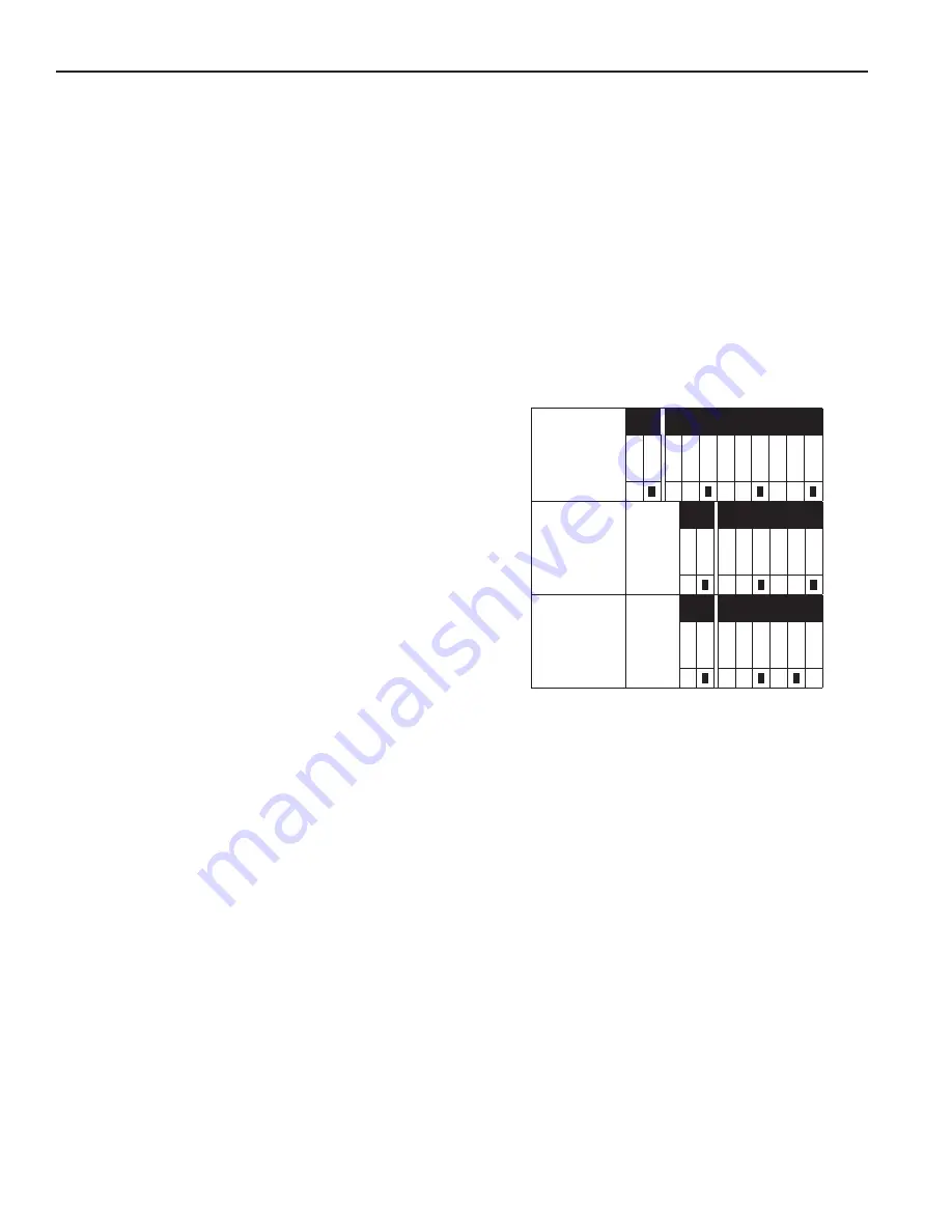
PXVC - (PT)
PXVC - T
PXVC - (All
other models)
FIGURE 3.
AO1
UI3
UI1
UI2
0...10V
0...20mA
0...10V
0...10V
0...20mA
0...20mA
0...20mA
0...10V
RT or contact
RT or contact
RT or contact
AO1
UI2
UI1
0...10V
0...20mA
0...20mA
0...20mA
RT or contact
RT or contact
RT or contact
0...10V
AO1
UI2
UI1
0...10V
0...20mA
0...20mA
0...20mA
RT or contact
RT or contact
RT or contact
0...10V
4
PXVC
AUGUST 2018
INSTALLATION:
The PXVC model controllers require careful attention to
the wiring diagrams based on the application to prevent
damage to the equipment. Failure to follow the diagrams
as presented may result in damage to the controller and
voidance of product warranty.
Review the controller specific applications and select the
application based upon your controller and application
needs for additional applications contact factory. Motorized
Control Valve Applications are available in bulletin R649b
WIRING NOTES
(refer to controller specific applications
for detailed diagrams):
The controller power pins 1 and 2 accepts 24 volts DC, refer
to Hansen drawing Figure 2 for reference.
INPUTS / OUTPUTS
Digital Output #1 is set up for pulse width operation and
requiring a 24-250VAC 3A power source. The output acts
as a switch, stopping and starting the valve (pins 3 and 4)
Digital Output #2 is setup to be the user alarms and requires
a 24-250VAC 3VA power source. The output acts as a switch,
stopping and starting the electricity flow (pins 5 and 6)
The analog output control signal does not require a power
source and should be connected directly to the Motorized
Control Valve as shown in Figure 2 (pins 7 and 8)
Universal Input #1 must be setup to properly and when
used as an analog (4-20mA) input a 24VDC power source
must be applied to the sensor as indicated in the diagrams
(pins 11 and 12)
(Excludes PXVC-PT) Universal Input #2 must be a continuous
circuit (switch closed) to operate as a remote interlock pins
(13 and 14).
SENSOR INSTALLATION:
Pressure Transducers
– Hansen recommends all pressure
transducers to be installed into a gauge valve which is
installed into the pressure port. This line of controller
is designed to work with transducers with a 4-20mA
signal. Pressure transducers are imprecise below -60F,
and standoffs are recommended. It is important that the
pressure transducer is installed as close to the outlet of
the heat exchanger (evaporator, shell and tube, plate and
frame, etc.) as possible to attain a precise reading.
Temperature Sensors
– Sensor should be installed as
close to the pressure sensing element as possible (where
applicable), or the outlet of the heat exchanger. Thermal
compound should be used to ensure sensor lag is kept to
a minimum. Immersion wells are highly recommended for
all applications.
Superheat / Temperature Applications
– When attempting
to read saturated vapor, intermittent liquid contacting the
sensing element will result in unstable sensor readings,
causing system instability. When operating a system where
liquid is present an immersion well should be used for
precise measurement. The well should be installed so
that it is constantly immersed in the liquid. Plumbing traps
are necessary to stabilize the flow of liquid and reduce
imprecision in the measurement. This is crucial for all
applications dependent on temperature measurements for
liquid or superheat control. Sensors should be installed per
wiring diagrams and as shown on the pipe at the 4’oclock
or 8’clock position as shown in Figure 5. For DX evaporator
setup, and the entire length of the pipe must be insulated.
Other Sensors
– Refer to the sensorproduct bulletin
(Pressure and Temp Sensor (HPT) bulletin PT100c,
Techni-Level probes P109, Vari-Level Probes P112)
SETTING UP THE CONTROLLER:
1. Verify jumpers on back of controller are set as follows:
2. Connect sensors and power. In superheat applications.
The pressure and temperature sensors should be placed
as close to one another as possible.
3. (Optional) Configure user desired alarms. Alarms close
the circuit between pins 4 and 6, and may be linked to
any device with a power rating between 24 - 250VAC
and 3A Max Current.
4. (Optional) Connect remote interlock. Interlock is active
when switch is closed and deactivated when switch is
open.
5. Best practice is to test function the unit, verifying output
matches expectations, using a process calibrator (4-
20mA by default) measuring analog signal output.
6. Switch off power
7. Connect outputs to valves and place into service
Contact Hansen if errors are encountered
PXVC UNIVERSAL CONTROLER


