background image


Hansa C60 RX O&M Manual 

– OM-015 Revision E 23/10/2019 

© Hansa Chippers 2019 

Safe operating procedure 


Wear  safety  equipment: 

Safety  glasses  and  hearing  protection 

must be worn at all times 


Wear  work  gloves:

  The  wearing  of  work  gloves  is  optional  but 

highly recommended - ensure that the gloves fit tightly 


Do NOT

 wear loose fitting gloves or gloves with long cuffs 


 Loose gloves may get snagged by branches, which could result in the operator being pulled into the chipper 


Tie long hair up 


Long hair could be snagged by a branch and may be pulled into chipper 


Wear clothes that sit tightly  


Avoid scarves and any items that can get caught in the chipper or snagged on branches 


Place the chipper on even ground and direct outlet chute onto soft ground 


Ensure exhaust is pointing away from the working area and downwind from the operator and onlookers  


Keep proper balance and footing at all times and stand at the same level as the chipper 


Do NOT

 climb onto the feed table to push material into the feed roller 


Ensure the chipper is positioned so that there is a minimum inlet table height of 600 mm off the ground 


Keep your face and body away from the inlet chute. Stand to the side of the inlet table while feeding material into the 
chipper 


Standing to the side gives better access to the control bar and helps in keeping clear from flying debris 


Feed only freshly cut material into the chipper 


Do NOT

 feed in materials covered in gravel, stones and dirt as this can rebound, injure the operator and damage 

the machinery  


Prune to a size that suits the chipper

’s capabilities


Pre-cut side branches  


T

he branch will ‘self

-

feed’ more ef

ficiently 


Keep the engine clean of debris and other accumulations  


This prevents damage to the engine or possible fire 


Feed limbs and branches through butt end first, leaving the bushy head on 


This helps guide the limb down the inlet chute  


It reduces spinning and the occurrence of ejection of small pieces back up the inlet chute  


Feed soft materials intermittently with branches  


The wood chips tend to clean out any soft residue left in the chipper 


The chipper can clog up with soft, wet or fibrous materials 


Keep well clear of the outlet chute discharge area, even when the chipper is not currently processing material 


High velocity, sharp discharge can cause serious injury 


Keep the outlet free of blockage 


If blockage occurs, turn the engine off and wait for rotor to stop spinning. Open the outlet chute and remove 
material until the outlet chute is clear 


Keep the feed roller free of blockage 


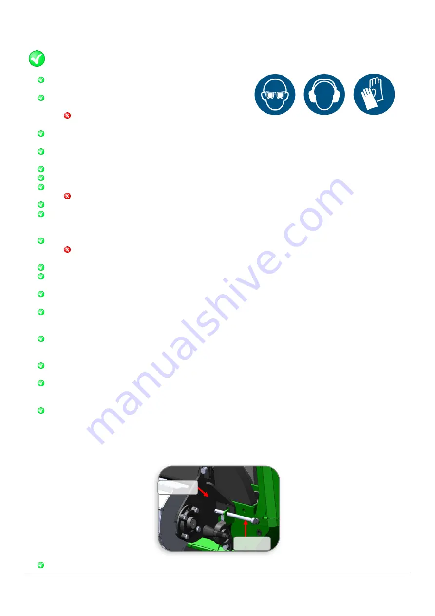
If  blockage  occurs,  turn  the engine  off  and  wait  for  rotor  to  stop  spinning.    Remove  the  feed  roller  guard  by 
unhooking the four rubber latches. Unhook the springs from the base of the chassis. Lift the swing arm up and 
insert the rotor pin (located underneath the control panel) into the tab on the housing to lock the swing arm in 
place (as per the diagram below). You may now safely clear the blockage. Remove the rotor pin, lower the feed 
roller, reposition the springs, then replace the guard  


Turn off the engine whenever you leave the work area 


DO:


Rotor pin 

Swing arm 

Summary of Contents for C60RX

Page 1: ...sachippers com HANSA AUSTRALIA 1800 426 722 info hansaproducts com au www hansaproducts com au Operation maintenance and safety manual All operators must fully read and understand this operator s manual before using the chipper Keep this manual for future reference ...

Page 2: ...NGINE LED PANEL 9 HOUR METER TACHOMETER 9 HYDRAULIC WINCH 9 EMERGENCY STOP 10 STARTING PROCEDURE 10 SHUTDOWN PROCEDURE 11 RUBBER TRACK DRIVE 12 TRACK CONTROL REMOTE PAIRING UNPAIRING PROCEDURE 12 TROUBLESHOOTING 13 MAINTENANCE SERVICE 14 KNIFE RE SHARPENING AND KNIFE REPLACEMENT 14 ANVIL ADJUSTMENT 17 BELT TENSION 17 BELT TENSION ADJUSTMENT 18 BELT REPLACEMENT 18 HYDRAULIC PUMP BELT ADJUSTMENT 18 ...

Page 3: ...and hire rental companies Do NOT use the chipper for any other purpose Organic wastes include Prunings stalks roots vegetable matter hay grass bark Branches Palm fronds Dead and hard timbers Note these will dull the knives faster Paper or cardboard Do NOT process Flax root balls Soil bones sand grit stones metal If you have any questions contact your authorised dealer Do NOT exceed 254 mm branch d...

Page 4: ...ective action Dust Injury or irritation of the eyes Respiratory irritation Wear safety glasses Process freshly cut materials and or wear a dust mask Exhaust Fumes Respiratory irritation Place the chipper in a manner that the operator or onlookers are not exposed to direct exhaust fumes Hot Exhaust Heat burns Keep bare hands and other body parts a safe distance away from hot exhaust Fire Heat burns...

Page 5: ... with local trailer transport regulations Track operation safety Pre driving checks Ensure the rotor is disengaged Ensure the inlet table is locked in the upright position Ensure the outlet chute is locked in the forward facing position All drivers must read all driving instructions before driving for the first time First time operators should familiarise themselves with the controls in an open fl...

Page 6: ...en as this could cause the machine to slide or tip into a steeper position Do NOT Drive the chipper within five metres of people including the operator It should be the responsibility of the driver to ensure that onlookers do not come within five metres of the machine while it is being driven Allow anyone within the immediate downhill area of the machine when it is being driven on steep terrain Th...

Page 7: ... operation checks have been done Setup the work site so there is no danger to traffic or public and provide adequate warnings Ensure the chipper is positioned on firm level ground Ensure the feed control bar is in the neutral position when starting the chipper Ensure the inlet table is clear of material when starting the chipper Ensure the throttle control lever is the initially in the idle positi...

Page 8: ... and dirt as this can rebound injure the operator and damage the machinery Prune to a size that suits the chipper s capabilities Pre cut side branches The branch will self feed more efficiently Keep the engine clean of debris and other accumulations This prevents damage to the engine or possible fire Feed limbs and branches through butt end first leaving the bushy head on This helps guide the limb...

Page 9: ...nd can rebound and injure the operator Put root balls and dead wood into the chipper This dulls the knives quickly Overload the chipper If the cutting rotor is slowing down feed the material in slower Transport the chipper while the engine is running Tamper with the engine governor settings on the chipper The governor controls the maximum safe operating speed and protects the engine and all moving...

Page 10: ...o a pre set level the feed roller stops and the branch stops feeding into the machine The engine then picks up in RPM and once it reaches a pre set speed the feed roller will start feeding again The feed wheel will also reverse back slightly after stopping reducing the friction between the wood and knives resulting in a quicker engine recovery The feed roller will only work once the engine is turn...

Page 11: ...ad 4 2 ton Line pull 1400 kg max Line speed 20m min Winch operation The winch is operated via a control panel near the base of the winch unit The switch on the right controls whether the winch is being extended or retracted The switch on the left toggles between remote control and manual control via the chipper body Note You may only operate the winch while the feed roller is in the neutral positi...

Page 12: ... normal shutdown procedure in addition to using the emergency stop Inspect the machine before resetting the emergency stop Under normal conditions do NOT use the emergency stop in place of the regular shutdown procedure Starting procedure Before proceeding ensure the safe setup procedure has been followed on page 5 of this manual Ensure the rotor is disengaged by winding the engagement handle in t...

Page 13: ...eed Controller section on page 8 to set the automatic feed control to the desired setting To shut the machine down move the throttle control lever to the idle position far right position Once the engine has been given enough time to slow down to idle speed about 10 15 seconds disengage the rotor by winding the engagement handle in the clock wise direction until the handle comes to a stop WARNING O...

Page 14: ...until the operator becomes familiar with the controls The speed setting should always be set to reduced speed when making precise manoeuvres and when mounting a trailer In the case that the remote control system cannot be operated such as a flat remote battery the machine can be switched to manual mode by flicking the switch inside the receiver cabinet to on While the machine is in manual mode the...

Page 15: ...te on by turning the remote s key clockwise to position 1 To pair the remote to the receiver press and hold the green start button on the remote for a few seconds until the green LED light on the remote flashes slowly The blue status LED light on the receiver located inside the electrical cabinet will flash quickly indicating that it is paired to the remote Drive the C60RX to the desired position ...

Page 16: ...n any loose parts Do NOT attempt to repair the chipper unless you are competent to do so The chipper stalls when material is being fed Auto Feed Control is not working Check that AFC is on Check the Autotrip setting is not at setting 0 or 20 manual mode If AFC is not working contact Hansa The feed roller is not turning Engine is not running at full throttle Increase the engine throttle to max RPM ...

Page 17: ...out in the rotor to lock it in place Using a 24 mm spanner and a 14 mm Allen key remove the knives from the rotor There are three bolts that you must remove on each knife to do so Be careful not to drop the bolts or knives into the chipper A stick magnet can be used to retrieve them if this does occur Measure the width of the knife and check that it will be at least 96 mm after sharpening If the k...

Page 18: ...ner Now tighten or loosen the two adjustment bolts Tightening these bolts will cause the anvil mounting plate to slide further along the slotted holes Ensure you tighten the two bolts evenly to avoid setting the anvil on an angle Once the correct anvil position has been set ensure the locking nuts on the adjustment bolts are tightened Additionally ensure the clamping nuts are torqued to 44 Nm Remo...

Page 19: ...he clamping bolts If the other side of the anvil hasn t been used yet rotate the anvil 180 degrees and place it back on the feed roller housing wall If both sides of the anvil are blunt remove the anvil and replace it with a new one Contact Hansa if a replacement anvil is required Tighten the clamping bolts back up using an 18 mm socket ensuring there is a spring washer between the clamping plate ...

Page 20: ... be replaced To remove the belts open the bonnet and fully disengage the belts The C60RX requires three SPB1410 belts Hydraulic pump belt adjustment The hydraulic pump is driven by a synchronous belt The belt does not require any tension however the belt should not have any slack either The belt can be adjusted by loosening the four mounting bolts using a 13 mm spanner and moving the pump pulley u...

Page 21: ...earings pivot points Points that need to be greased are as follows as per the diagram below 1 Two bearings on the rotor shaft one under the engine cover and the other above the inlet opening 2 Two bearings on the feed wheel 3 Two bearings on either side of the feed wheel pivot 1 2 3 4 5 ...

Page 22: ...manual Ensure the correct engine oil is used C60RX Track maintenance and rubber track tension Please refer to the Hinowa Tracked Undercarriage Operating and Maintenance Manual for full maintenance details Key maintenance points Each drive motor contains a reduction gearbox The oil in this gearbox needs to be replaced after the first 100 hours then at 1000 hour intervals thereafter Refer to track m...

Page 23: ...he grub screws are tightened evenly so the pulley is tightened evenly 6 The gap between the end of the sensor and the sensing plate should be approximately 3 mm Adjust the sensor accordingly If it is set further away then the sensor may not work properly and therefore the AFC will not work Replacing rotor bearing on inlet chute side of rotor It is recommended to have this bearing replaced by a spe...

Page 24: ...eck sharpen or replace Belt guarding remove and clean chip build up Drive belts tension check adjust Hydraulic pump belt tension check adjust Fan belt check Engine oil filter change Nuts bolts check torque Track gearbox oil initial change Initial Hydraulic system check Spring mounting check U bolts Brake fluid check Hydraulic oil filter replace Battery electrolyte level terminals check Engine fuel...

Page 25: ...id cooled 4 cylinder turbo charged Type of fuel Diesel Capacities Fuel tank 75 L Hydraulic oil tank 100 L Chassis Frame description 100 x 50 x 5 mm RHS Width 1200 mm Tracked Undercarriage Speed 5 km hr max fully proportional Track drive Remote control Undercarriage material Rubber Cutting System Disc speed 1620 RPM Disc diameter 800 x 40 mm Shaft diameter 60 mm Knives Four Feed System Feed opening...

Page 26: ...ippers 2019 24 Decals Decal Description Location General machine safety and inlet chute safety Side of inlet chute both sides Inlet chute safety Inside of inlet table Rotor engagement control Belt guard next to engagement arm Throttle control Below throttle lever ...

Page 27: ... OM 015 Revision E 23 10 2019 Hansa Chippers 2019 25 Weekly service checks Rotor cover back Stop procedure Feed roller cover Start procedure Feed roller cover Outlet chute safety Outlet chute Service schedule Rotor cover back ...

Page 28: ...ansa Chippers 2019 26 Diesel tank Diesel tank Hydraulic oil tank Hydraulic oil tank Feed roller motor safety Feed roller motor Feed roller motor safety keep clear Top face of feed roller cover Feed roller cover safety Do not open Top face of engine bonnet ...

Page 29: ...015 Revision E 23 10 2019 Hansa Chippers 2019 27 Feed control bar Feed control bar Winch safety Winch boom control panel side Rotor cover safety Rotor cover Recommended oil fill level Aligned with 80 to the left of the fuel gauge ...

Page 30: ...rranty is available to domestic non commercial and commercial customers excluding commercial customers in the business of plant equipment hire All HANSA products that have not complied with the Extended Warranty registration and maintenance requirements are entitled to the Non Registered warranty period set out below Any authorised HANSA dealer is further authorised to repair or replace any part w...

Page 31: ... you purchased your HANSA product Conditional Warranty This is a HANSA extended warranty period for products that are Purchased from an authorised HANSA Dealer Registered at the time of sale through the Hansa Chippers website www hansachippers com registration Serviced by a HANSA Dealer in accordance with the Hansa service schedule using genuine HANSA parts Meeting all other warranty requirements ...

Page 32: ...Operation Instruct the owner operator on operating procedures and techniques Safety Instruct owner operator on safety procedures Maintenance Explain the maintenance requirements and the importance of following the maintenance schedule to the owner operator Manual Emphasise the importance of reading and understanding the manual in full before initial operation of the chipper It is the retailers res...

Reviews: