


27
Hangar 9 RV-8 Assembly Manual
Step 10
The battery is mounted inside the fuselage using hook
and loop straps. The position of the battery can be moved
forward or aft to adjust the Center of Gravity of your model
once it has been completely assembled.
note
: If you are using the new Thunder Power
Generation 2 batteries or equivalent then the cooling
hole is not mandatory, but strongly recommended.
Step 11
Use a hobby knife with a #11 blade and ruler to cut the air
cooling template from Page 47 of this manual.
Step 12
Carefully fold the template along the fold lines. This will
assist in positioning the template on the bottom of the
fuselage.
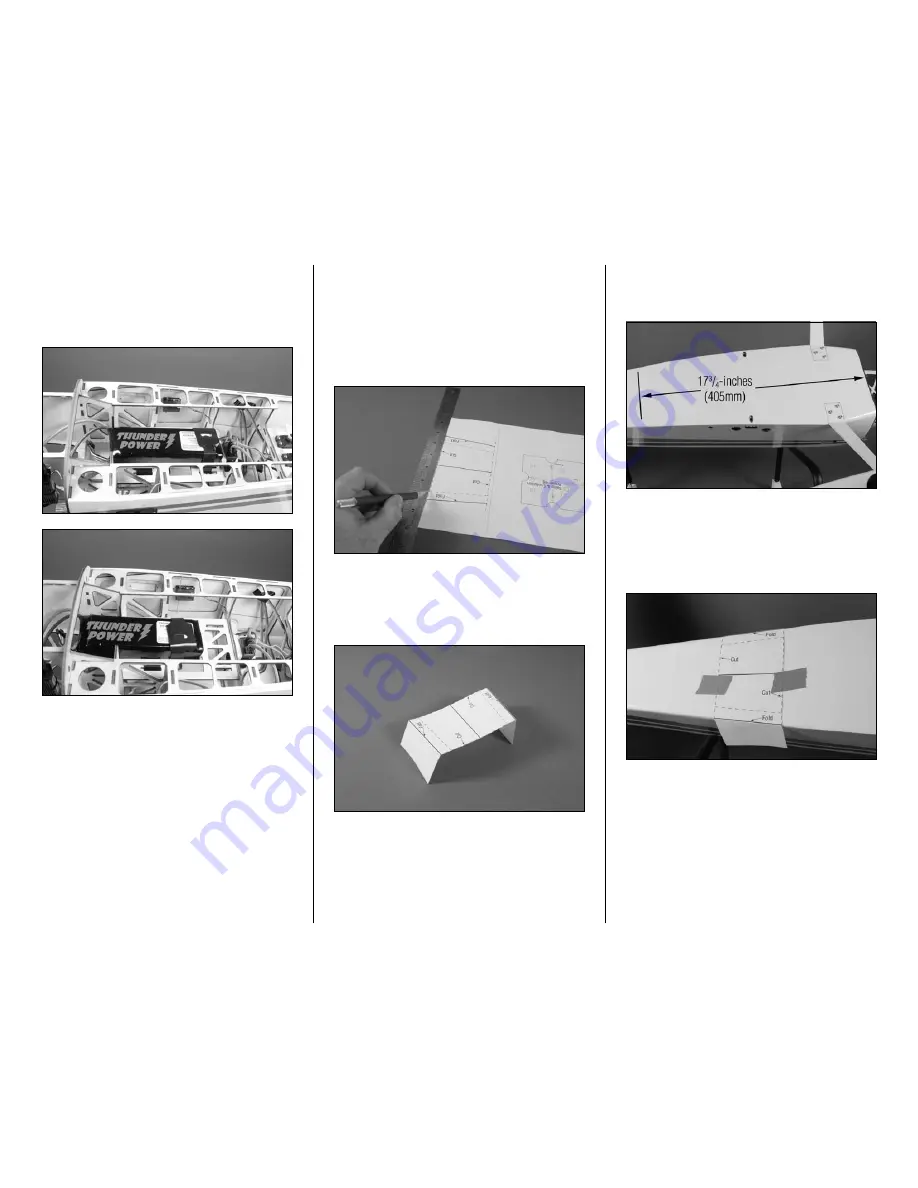
Step 13
Use a ruler to measure back 17
3
/
4
-inches (450mm) back
from the point on the fuselage shown in the photo below.
Step 14
Position the template so the front edge is at the mark made
in the previous step. The folds will help in centering the
template on the bottom of the fuselage. Use low-tack tape to
secure the template to the bottom of the fuselage.