background image

21

Section 6: Hinging the Vertical and Horizontal
Stabilizers

1.

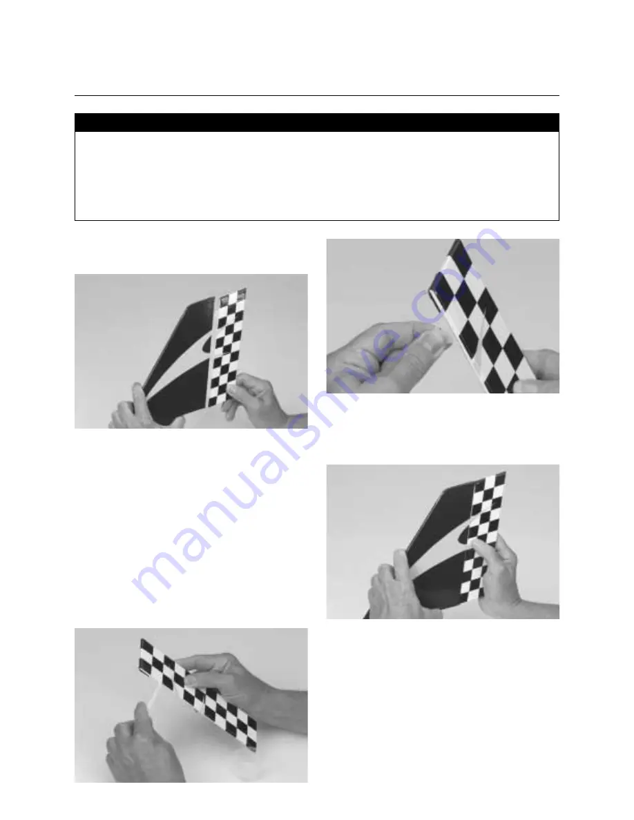
Carefully remove the rudder from the vertical stabilizer by

pulling straight out with even pressure.

2.

Remove the three hinges from the rudder and flex them along

the hinge line so they move freely.

3.

Mix a small amount, approximately 1/4 oz., of 30-minute

epoxy. Using either a mixing stick, scrap of wood or epoxy brush,
sparingly apply the epoxy inside each hinge slot on the rudder.
Additionally, apply a small amount of epoxy to the top and
bottom one-half of each hinge.

It’s necessary to roughen the surface of the hinges with
sandpaper so the epoxy will adhere better to the hinge.

Insert the hinges into the rudder until the hinge line is even with
the leading edge of the rudder.

4.

Apply epoxy to the remaining half of each hinge and into the

hinge slots in the vertical stabilizer as well. Replace the rudder
onto the vertical stabilizer.

• Horizontal stabilizer with elevator 
• Vertical stabilizer with rudder

• 30-minute epoxy 
• Mixing stick 
• Epoxy brush 
• Paper towels 
• Rubbing alcohol 
• Sandpaper (medium)

Parts Needed

Tools and Adhesives Needed

Summary of Contents for Hangar 9 Solo

Page 1: ...Length 45 1 2 sq Wing Area 720 in Weight Approx 6 6 1 4 lbs Recommended Engines 40 48 2 cycle 45 56 4 cycle Easy to fly great for first time pilots Excellent self righting flight characteristics 90 pre built and covered in pre printed heat shrinkable PVC All hardware included Three trim schemes to choose from Sport Star Strike ...

Page 2: ...Stabilizers 21 Section 7 Installing the Tail 23 Section 8 Installing the Control Horns 27 Section 9 Assembling and Installing the Fuel Tank 29 Section 10 Installing the Main Landing Gear 32 Section 11 Installing the Nose Gear 34 Section 12 Installing the Engine 36 Section 13 Installing the Spinner 37 Section 14 Installing the Radio and Centering the Servos 38 Section 15 Installing the Linkages 42 ...

Page 3: ... out an experienced flier to help you with your first flights you should do this with any R C aircraft Your local hobby shop should be able to suggest pilots who can assist you Should you have any questions regarding this kit please contact the Horizon Service Center at 217 355 9511 WARNING An R C aircraft is not a toy If misused it can cause serious bodily harm and damage to property Fly only in ...

Page 4: ...d file Razor saw Moto Tool with sanding drum Wax paper Mixing stick Epoxy brush 90 degree triangle File Medium sandpaper Masking tape Straight edge Measuring device e g ruler tape measure Scissors Paper towels Rubbing alcohol Felt tipped pen Fuel tubing 9 10 medium Clips clothespins binder clips Hobby knife with 11 blade Radio packing foam Additional Tools and Supplies Required not supplied ...

Page 5: ...th rudder E Horizontal stabilizer with elevator Others 1 Pushrod and Accessories 2 1 8 plywood die cut parts 3 Main landing gear 4 Nose landing gear 5 Spinner 6 Hardware bag 7 Plastic parts tree 8 Foam wheels 9 Fuel tank and hardware 10 Wood control dowels 11 Wing mounting dowels 12 Trim tape A B C 12 9 2 7 8 10 11 1 4 3 5 6 E D ...

Page 6: ...ack JR F400EX 10x6 propeller MDS 40FS engine AeroBlend quart 10 Hangar 9 Start Up Field Pack Flight tote 4 way wrench Glow plug igniter Chicken stick Manual fuel pump Glow plugs 6 Airplane Fuel HAN3110 Skypack Pilot Support Package HAN001 Propeller MAS1060 Glow Plug Igniter with Charger MCD101 Glow Plug Wrench HAN2510 Glow Plug HAN3000 3005 Manual Fuel Pump HAN118 Field Equipment Required 64 Rubbe...

Page 7: ... 131 Cleaner Towels Extra Glow Plugs HAN 3000 3005 Misc Tools After Run Fuel HAN3100 Power Panel HAN106 Optional Field Equipment The HANSTART Start up Field Pack includes Flight tote 4 way wrench Glow plug igniter Chicken Stick Manual fuel pump Glow plugs Start up Field Pack HANSTART ...

Page 8: ... amount approximately 1 4 oz of 30 minute epoxy Using either a mixing stick or a small piece of scrap wood apply the epoxy sparingly inside each hinge slot on the aileron Additionally apply a small amount of epoxy to the top and bottom half of each hinge Insert the hinges into the aileron until the hinge line of the hinge is even with the leading edge of the aileron Note Do not apply epoxy into th...

Page 9: ...n on the right wing half Ensure that the hinges are properly aligned and that the aileron torque rod presses into its respective hole in the aileron Note that the gap between the aileron and the wing should remain a constant 1 16 or as tight as possible without affecting the free movement of the aileron 8 Carefully wipe off any excess epoxy using a paper towel and rubbing alcohol 9 Repeat Steps 1 ...

Page 10: ...oiner Align the upper and lower edges of all three joiners as well as the area which has the slight V shape 3 Clamp the three joiners together using four clothespins or clips Make sure the joiners remain aligned and the clamps are firmly attached 4 Wipe away the excess epoxy using a paper towel and rubbing alcohol being careful not to disturb the alignment of the wing joiners Note The excess epoxy...

Page 11: ...stic wing tip joins the end of the wing panel If the angle measurement is not 41 2 very lightly sand the wing rib on just one of the wing panels Refit the wings and re check the angle 9 Separate the wing halves and remove the dihedral brace 10 Place the wing halves on the flat surface so the bottoms are facing upward Note the wing root the exposed wood end of the wing halves as shown below Using a...

Page 12: ... the center line making sure the V of the dihedral brace is positioned correctly with the wing upside down the V will also be upside down 14 Apply a generous amount of epoxy into the wing cavity of the other wing half 15 Smear epoxy on all sides of the exposed area of the dihedral brace and uniformly coat both wing roots with epoxy CONTINUED Section 2 Joining the Wing Halves ...

Page 13: ...ly masking tape at the wing joint to hold the wing together securely while the epoxy cures Place the wing on a large flat surface With one wing panel lying flat on the surface the opposite wing tip should be propped up exactly 41 2 from the surface Allow the wing joint to dry overnight Note It s a good idea to place a sheet of waxed paper under the center joint of the wing so any excess epoxy does...

Page 14: ...around the outside upper and lower parallel edges of the servo tray using a felt tipped pen These marks will serve as the guides for cutting the servo tray support slots later in this section Additionally place a mark along each of the outside vertical edges of the tray These marks will be the outer edges of the servo tray support slots 6 Using a felt tipped pen trace around the inside edge of the...

Page 15: ...supports 9 Using a sharp hobby knife carefully cut through the balsa wood and the covering along the lines that were drawn in Step 6 of this section Remove the excess balsa from this hole 10 Trial fit the aileron servo into the servo tray as well as into the hole which was cut in the previous step Position the servo so the servo horn is closest to the trailing edge Depending upon the dimensions of...

Page 16: ...he joint between the aileron servo tray and the aileron servo support Note Thick CA can be used instead of epoxy for this procedure 12 Repeat this procedure for the opposite aileron servo support making sure the aileron servo supports and the servo tray remain perpendicular to one another Allow the epoxy or CA to dry completely before proceeding to the next step CONTINUED Section 3 Installing the ...

Page 17: ...y excess epoxy with a paper towel and rubbing alcohol Allow the epoxy to cure 14 Locate the wing center tape and remove the adhesive backing Starting at the rear of the aileron servo tray wrap the tape completely around the wing joint seam to the rear of the servo tray Gently pulling on the tape while pressing it down onto the wing will provide a smooth seam Cut off any excess tape with a pair of ...

Page 18: ...chieved remove the three servos from the servo tray Trial fit the servo tray into the fuselage noting the correct orientation The single servo cut out should be closest to the front of the fuselage Note The tray should seat snugly into the notches in the servo tray support and fuselage former If it s too tight use a file or sharp hobby knife to remove a small portion of the tab from the servo tray...

Page 19: ...an epoxy brush apply epoxy to the servo tray in the areas that will come in contact with the servo tray support and the fuselage sides Install the servo tray into the fuselage noting the correct orientation as shown at the right CONTINUED Section 4 Assembling the Fuselage ...

Page 20: ...e fuselage 3 Mix a small amount approximately 1 4 oz of 6 minute epoxy Using an epoxy brush apply a thin coat of epoxy to the wing dowels as shown to prevent the dowels from becoming fuel soaked during flight The epoxy will also prevent the dowel from moving in the holes 4 If necessary wipe away the excess epoxy using a paper towel and rubbing alcohol being careful not to disturb the alignment of ...

Page 21: ...tionally apply a small amount of epoxy to the top and bottom one half of each hinge It s necessary to roughen the surface of the hinges with sandpaper so the epoxy will adhere better to the hinge Insert the hinges into the rudder until the hinge line is even with the leading edge of the rudder 4 Apply epoxy to the remaining half of each hinge and into the hinge slots in the vertical stabilizer as ...

Page 22: ...ly wipe away any excess epoxy using a paper towel and rubbing alcohol 6 Repeat this procedure to install the elevator to the horizontal stabilizer CONTINUED Section 6 Hinging the Vertical and Horizontal Stabilizers ...

Page 23: ...tal stabilizer in place on the fuselage Check the alignment of the horizontal stabilizer by measuring from a fixed point along the center line of the fuselage to the leading edge on each side of the horizontal stabilizer The distance to the tip of the horizontal stabilizer must be equal on both sides If it s not adjust the stabilizer until the measurements are the same Fuselage Wing Horizontal sta...

Page 24: ...alignment of the stabilizer The pencil should leave a light indentation in the covering 7 Remove the horizontal stabilizer from the fuselage Using a straight edge make sure the lines drawn are straight Using a sharp hobby knife carefully cut away the covering inside the lines marked above Be careful not to cut into the wood as doing so will weaken the structure 8 Mix approximately 1 8 ounce of 30 ...

Page 25: ...al stabilizer where it meets the fuselage Again the pencil should leave a light indentation in the covering of the vertical stabilizer 13 Remove the vertical stabilizer from the fuselage Using a sharp hobby knife carefully cut away the covering below the lines drawn in the previous step Do not cut into the balsa wood as this will affect the structural integrity of the stabilizer 14 Mix up approxim...

Page 26: ...it s seated properly on the horizontal stabilizer Precisely align the vertical stabilizer as described in Step 11 of this section 16 Secure the vertical stabilizer in place using masking tape and allow the epoxy to cure completely CONTINUED Section 7 Installing the Tail ...

Page 27: ... the control horn must be positioned such that it s centered over the hinge line and centered in relation to the slot that was opened in the previous step 3 When you re satisfied with the alignment of the control horn mark the mounting hole positions with a felt tipped pen Control horns 2 Control horn back plate 2 Control horn screws 4 Fuselage with vertical and horizontal stabilizers Drill 1 16 d...

Page 28: ...with a felt tipped pen This mark will serve as the center of the rudder control horn 7 Center the control horn over the mark made in the previous step making sure it s centered over the hinge line Again mark the location of the control horn mounting hole positions when you re satisfied with the alignment 8 Remove the rudder control horn and use a 1 16 drill bit to drill these two mounting holes 9 ...

Page 29: ...nk vent tube which will be connected to the pressure fitting of your motor s muffler when the engine is plumbed in Section 16 Note Bend this tubing slowly and carefully so it doesn t kink Fuel tank Fuel tubing not supplied Fuel clunk Aluminum tube short pickup Aluminum tube short optional fill tube Aluminum tube long vent Silicone tubing Rubber stopper 3mm self tapping screw Fuselage Foam collar M...

Page 30: ...small inside cap and the bumps face away from the black rubber stopper The large outside cap and the bump go away from the black rubber stopper 6 Locate the silicone fuel tubing and the metal clunk Insert the fuel clunk into one end of the fuel tubing This assembly will be used for the fuel pickup inside the fuel tank 7 Install the open end of the fuel tubing on the shorter aluminum tubing 8 Caref...

Page 31: ... piece and a 4 1 2 piece Attach the 4 1 2 piece of fuel tubing to the vent tube Attach the 3 1 2 piece to the fuel tank pickup tube To make identification easier attach a piece of masking tape to the fuel vent tubing to distinguished it from the fuel pickup tubing Or you can simply remember the fuel vent tubing is the longer piece 4 1 2 11 Place the foam fuel tank collar around the neck of the fue...

Page 32: ...epoxy has cured locate the two main landing gear struts and insert them into the landing gear slots as shown Make sure the ends fit into the holes in the edges of the slot 4 Remove the two landing gear straps from the plastic parts tree and place them across the landing gear struts so they are evenly spaced on the landing gear Using a felt tipped pen mark the location of the two landing gear mount...

Page 33: ...anding gear mounting straps Using the four 2 6mm self tapping screws from the hardware bag fasten the landing gear to the bottom of the fuselage as shown 7 Place the wheels on the ends of the landing gear struts and secure them with the supplied wheel collars Place a wheel collar on both sides of the wheel Use thread lock on the wheel collar screws CONTINUED Section 10 Installing the Main Landing ...

Page 34: ...to the nose gear between the nylon motor mount and metal motor mount as shown Insert until the coil is just below the bottom of the fuselage 4 Adjust the nose gear control horn until the arm is parallel with the firewall Note The axle of the nose wheel should be parallel to the firewall as well Apply thread lock to a 3mm screw and secure the steering arm in place CAUTION Do not overtighten the 3mm...

Page 35: ...e gear strut and hold in place with a plastic spacer from the plastic parts tree a 5 32 wheel collar and a 3mm screw Be sure to secure the screw with thread lock Note Final assembly of the nose gear will be done in the section on control linkage hookup CONTINUED Section 11 Installing the Nose Gear ...

Page 36: ...ace one engine mounting bracket across each of the engine mounting lugs as shown Note The dimpled side of the engine mounting bracket is the bottom and therefore the smooth surface should face upward 4 Insert one 4x20mm screw into each of the engine mounting bracket holes Press one of the 4mm nuts into the corresponding receptacles on the bottom of the motor mount Apply thread lock to secure the n...

Page 37: ...opeller on the crankshaft and position it so it seats correctly against the spinner back plate Next install the engine washer and the prop nut onto the crankshaft and tighten securely 3 Attach the spinner to the spinner back plate using the two screws provided in the hardware bag Spinner Spinner back plate Spinner screws 2 Fuselage with motor mounted Phillips screwdriver medium Parts Needed Tools ...

Page 38: ...ng servos It s helpful to label each servo as to its function i e rudder elevator throttle by using a piece of masking tape attached to the connector end of each servo lead This will be helpful for connecting the servos to the receiver after they re installed in the servo tray Note also the use of R E and T to identify where the servos are placed on the servo tray Position the three servos in the ...

Page 39: ... the compartment in front of the servo tray Cut out another layer of foam that s identical in size however cut an opening in the center of this foam so it will accept the receiver battery pack Place another solid layer of foam on top of this layer Cut another layer of foam to accept the receiver The final layer of foam should be solid 7 Place the layers of foam with the battery and receiver in the...

Page 40: ... the hole cut in the previous step Using a felt tipped pen mark the screw holes on either end of the switch plate 10 Remove the switch plate from the fuselage Drill the two mounting holes as marked using a 1 16 drill bit 11 Reposition the switch plate as shown and place the switch on the inside of the fuselage Using the two screws supplied with the switch attach the switch to the fuselage The sugg...

Page 41: ...at order You have just electrically centered your servos Note You can turn your transmitter and receiver off anytime but to keep the electrical center of your servos turn the receiver off first then the transmitter To turn on again turn on the transmitter first then the receiver 13 Replace the servo horns on each servo so the arms are 90 degrees to the center line of the fuselage as shown in the p...

Page 42: ...ut into 7mm length over the clevises This will provide extra insurance against the clevises accidentally coming open 5 Center the aileron servo using the method described in Section 14 Step 12 13 and using a felt tipped pen place a mark on the unthreaded end of the aileron pushrods where they pass their respective servo arm Aileron horns 2 Long threaded music wire rods 2 Short threaded music wire ...

Page 43: ...d 9 Locate one of the short threaded rods one piece of the extra length of rod from Step 6 one piece of the yellow heat shrink tubing one clevis and the shorter pushrod dowel 10 Using a sharp hobby knife or a pair of scissors cut the heat shrink tubing into two equal pieces 11 Cut 7 of the threaded rod measured from the threaded end This rod will be used to attach the clevis to the rudder control ...

Page 44: ...end of the pushrod dowel and shrink it into place using a heat gun The completed rudder pushrod is shown below 18 Carefully cut away the covering on the aft side at the tail where the rudder pushrod will exit 19 Insert the rudder pushrod assembly threaded end first into the fuselage so the threaded end exits the rudder pushrod hole in the fuselage 20 Screw on a clevis 12 complete turns Fasten the ...

Page 45: ... you will need to carefully cut away the plastic covering at the rear of the fuselage where the elevator pushrod will exit 25 Repeat Steps 9 17 of this section to assemble the elevator pushrod Note The elevator pushrod dowel is long so cut the threaded music wire 5 from the threaded end of the rod Cut the remaining piece of the music wire to a 6 length The threaded end will connect to the elevator...

Page 46: ...t the threaded rod unthreaded end first through the 1 16 hole in the fuselage firewall The rod should exit into the radio servo tray compartment 34 Attach the clevis to the throttle lever of the carburetor opening the carburetor halfway Remember to install a small piece of fuel tubing on the clevis to make sure it doesn t accidentally open 35 Center the throttle servo Using a felt tipped pen mark ...

Page 47: ...rvo arm 42 Be sure the rudder servo is centered Using a felt tipped pen place a mark on the unthreaded end of the steering pushrod where it passes the nose wheel steering arm 43 Using z bend pliers make a z bend at the marked location on the rod Cut off the excess rod Helpful Hint Removal of the steering pushrod clevis may make forming the z bend easier 44 Insert the z bend into the outermost hole...

Page 48: ...w plug if you have not done so 2 Connect the vent tube from the fuel tank to the pressure fitting on the muffler Remove the masking tape at this time 3 The remaining tube should be attached to the carburetor fuel inlet nipple Fuselage with engine mounted Muffler Hobby knife Phillips screwdriver medium Parts Needed Tools and Adhesives Needed ...

Page 49: ...urn the wing and plane if assembled upside down and about where the center sheeting stops on each side of the wing measure back 3 3 4 from the leading edge of the wing and make a mark with your felt tipped pen This is the balance point 2 With your model fully assembled but without fuel turn the model upright and pick it up with one finger at each of the balance marks you made earlier If balanced p...

Page 50: ...trailing edge of the aileron Note Aircraft orientation is as if you are sitting in the cockpit looking forward 3 If the ailerons do not move in the correct direction switch the aileron servo reversing switch on the transmitter 4 If the ailerons do not move far enough either move the pushrods out on the servo horn farthest hole from center both sides or move the torque rod horns down farther on the...

Page 51: ... The rudder should move approximately 7 8 measured at the trailing edge of the rudder 13 If the rudder moves right switch the rudder servo reversing switch on the transmitter 14 If the rudder doesn t move far enough either move the pushrod out farther on the servo horn or move the clevis in on the rudder control horn If the rudder moves too much either move the pushrod in on the servo horn or out ...

Page 52: ...t to fully closed by screwing in the clevis on the pushrod thus shortening the rod length 22 With the radio still on move the throttle trim lever up to its centered position This should open up the carburetor barrel slightly 1 32 1 16 and allow the engine to idle satisfactorily To shut the engine off from the transmitter simply move the throttle stick and trim lever all the way down 23 Now move th...

Page 53: ... switch to correct the direction Note Mode II transmitter shown in diagram Step 2 Check that each clevis is securely snapped into position Step 3 Check that all servo horn screws are tight Step 4 Charge the transmitter and receiver battery per the instructions included with your radio system Step 5 Read and follow all the instructions included with the engine and follow the recommended break in pr...

Page 54: ...that all controls aileron elevator throttle rudder move in the correct direction Step 3 Be sure that your batteries are fully charged per the instructions included with your radio Pre Flight at the Flying Field Adjusting the Engine Step 1 Completely read the instructions included with your engine and follow the recommended break in procedure At the field adjust the engine to a slightly rich settin...

Page 55: ...oors 8 I will not operate models with metal bladed propellers or with gaseous boosts in which gases other than air enter their internal combustion engine s nor will I operate models with extremely hazardous fuels such as those containing tetranitromethane or hydrazine 9 I will not operate models with pyrotechnics any device that explodes burns or propels a projectile of any kind including but not ...

Page 56: ... s pitch axis Pulling the transmitter s control stick toward the bottom of the transmitter adjusts the elevator upward and the airplane begins to climb Push the control stick forward and the airplane begins to dive Expanded Scale Voltmeter ESV This device is used to check the voltage of the battery pack Flight Box The box in which you store and transport your flying equipment is called a flight bo...

Page 57: ...m A removable arm or wheel that connects the servo to the pushrod Also called servo horn Spinner Term describing the nose cone that covers the propeller hub Switch Harness This switch is commonly located on the fuselage and governs the on off mechanism for the flight pace Tachometer A device the measures the engine s RPM rotations per minute by counting light impulses that pass through the spinnin...

Page 58: ...58 NOTES ...

Page 59: ...59 NOTES ...

Page 60: ... Copyright 1998 Horizon Hobby Distributors Inc ...

Reviews: