29
Hangar 9 Alpha 40 ARF Assembly Manual
Step 12
Repeat Steps 10 and 11 to install the second screw.
Throttle Linkage Connection
Required Parts
Fuselage
Pushrod snap link
Transmitter
Required Tools and Adhesives
Pliers
Felt-tipped pen
Drill bit: 5/64-inch (2mm)
Pin vise
Diagonal cutters
Note
: This section covers the installation and
connection of the throttle linkage. If you have installed
an electric power system you can skip this section of
the manual.
Step 1
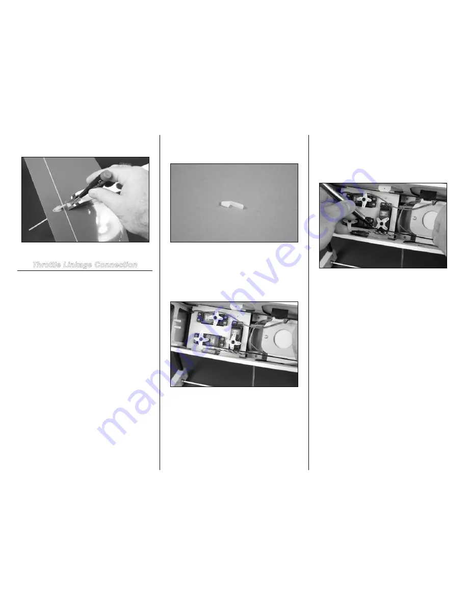
Locate the pushrod snap link. This will be used to secure the
pushrod wire to the throttle servo horn.
Step 2
With the radio system on, move the throttle stick and trim on
the transmitter to the center. Remove the throttle servo horn
from the servo. Rotate the horn so the arm that aligns with
the throttle pushrod measures 1/2-inch (13mm) from the
center of the horn, which aligns with the outer hole of the
servo horn.
Step 3
Move the throttle stick to the closed throttle position at the
transmitter. Pull the throttle linkage so the carburetor at the
engine is closed. Use a felt-tipped pen to mark the pushrod
wire where it crosses the hole on the servo horn that is 1/2-
inch (13mm) from the center of the horn.
Step 4
Use the radio to move the servo to the open throttle position.
Push the linkage to open the carburetor. The line made in the
previous step should align with the same hole on the servo
horn. If the line is further forward than the servo horn, you
will need to use a longer servo horn or connect the clevis at
the carburetor closer to the center of the carburetor. If the
line does not move far enough you will need to use a shorter
servo horn or connect the clevis at the carburetor to a hole
farther away from the center or the arm. Adjust as necessary
so the servo movement is correct for your engine.
Note
: If using a computer radio you can use the travel
volume to adjust for minor differences. It is best to set it as
close mechanically to result in linear travel of the throttle.


