background image

28

Hangar 9 Alpha 40 ARF Assembly Manual


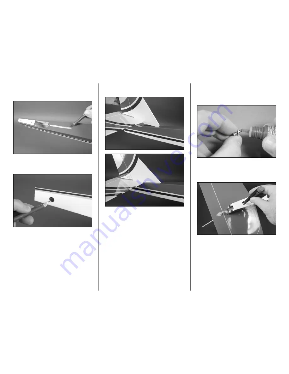
Step 7

Use a hobby knife to remove the covering from the slot on 

the top of the fuselage for the fin.


Step 8

Use a hobby knife with a #11 blade to remove the covering on 

the bottom of the fuselage for the stabilizer attachment screw.


Step 9

Slide the fin into position on the fuselage as shown.

o


Step 10

Locate a #4 washer and 3mm x 10mm machine screw. Slide 

the washer onto the screw, then apply a small amount of 

threadlock on the screw.

o


Step 11

Insert the screw into the hole in the fuselage and through 

the stabilizer to the preinstalled blind nut on the top of the 

stabilizer. Use a #2 Phillips screwdriver to tighten the screw.

Summary of Contents for Alpha 40 ARF

Page 1: ...ifications Wingspan 63 in 1600mm Length 52 5 in 1334mm Wing Area 710 sq in 45 8 sq dm Weight 5 5 5 lb 2 27 2 49 kg Radio 4 channel minimum Engine 40 46 2 stroke glow Power 25 EP Alpha 40 ARF Assembly Manual ...

Page 2: ...follow all the instructions and warnings in the manual prior to assembly setup or use in order to operate correctly and avoid damage or serious injury Product Support For technical assistance with this product please contact the appropriate Horizon Product Support office See page 51 Specifications Wingspan 63 in 1600mm Length 52 5 in 1334mm Wing Area 710 sq in 45 8 sq dm Weight 5 5 5 lb 2 27 2 49 ...

Page 3: ... Throttle 2 56 x 28 inch one end threaded pushrod 2 Elevator and rudder Bagged separately Fuselage with hatch 1 Right wing panel with aileron 1 Left wing panel with aileron 1 Vertical fin 1 Horizontal stabilizer 1 Aluminum wing tube 12mm x 318mm 1 Fuselage 9 oz 260cc fuel tank assembled 1 4 x 5 8 inch wood screw 1 Tank support tray 3mm x 12mm socket head cap screw 2 Fuselage lower hatch 4 flat was...

Page 4: ...ollow the manufacturer s instructions when using and disposing of any batteries Mishandling of Li Po batteries can result in fire and explosion causing serious injury and damage SmalL Parts This kit includes small parts and should not be left unattended near children as choking and serious injury could result Safe Operating Recommendations Inspect your model before every flight to make certain it ...

Page 5: ...ng around areas where the colors overlap to prevent separating the colors HAN100 Heat Gun HAN150 Covering Glove HAN101 Sealing Iron HAN141 Sealing Iron Sock Radio Systems Requirements Spektrum Radio System recommended DX6i 6 channel radio or greater with receiver SPM6600 DS821 Digital Sport Servo 4 JRPS821 6 inch Servo Extension JSP98110 Receiver Battery 2300mAh JRPB5006 JR Switch Chargeswitch JRP...

Page 6: ...ystem Follow the instructions provided with your radio system to do so Note Make sure to turn off both the transmitter and receiver before unplugging the servos Important You will need to connect a 6 inch 152mm extension in the Aileron port of the receiver to connect to the servo used for the Ailerons Leave the extension plugged into the receiver when unplugging the servos Step 2 Prepare the servo...

Page 7: ...0 locknut 4 Safety tubing Clevis 2 56 x 161 4 inch throttle pushrod 4 40 x 1 inch socket head screw 4 8 32 x 1 inch socket head screw 4 Required Tools and Adhesives Nut driver 1 4 inch Threadlock Hex wrench or ball driver 3 32 inch 9 64 inch Step 1 Locate the necessary hardware to install the engine on your model Step 2 Slide a 8 washer on an 8 32 x 1 inch socket head screw Slide the screw into th...

Page 8: ...ightened at this time so the mount can be positioned for your engine The bolts wil be tightened once the engine has been secured to the mounting rails Step 4 Place a 4 washer on each of the four 4 40 x 1 inch socket head bolts Slide the screws through the holes in the engine mount flange Step 5 Place the engine on the mounting rails The screws will go through the holes in the rails Thread a 4 40 l...

Page 9: ... a 1 4 inch nut driver to tighten the hardware securing the engine to the engine mounting rails Step 8 Use a hobby knife to cut a 1 4 inch 6mm piece of tubing from the 2 inch 52mm safety tubing Step 9 Slide the piece cut in the previous step on a nylon clevis Thread the clevis 10 turns onto the threaded end of the 2 56 x 161 4 inch throttle pushrod wire Step 10 Slide the pushrod wire into the tube...

Page 10: ...rmine the internal positioning of the vent line This is important as the vent line must face to the top of the fuselage for the engine to run properly You may want to place a piece of tape on the tube that corresponds to the vent line for easier identification later Clunk Vent Line Top View Side View Vent Line faces top of fuselage To Muffler To Carburetor Step 3 Insert the fuel tank in the fusela...

Page 11: ... CA to glue the braces to the fuselage sides Step 7 Use a hobby knife with a 11 blade to expose the two holes for the fuselage hatch mounting screws Step 8 Slide the fuselage hatch in position on the fuselage The tabs will lock the front of the hatch in position Step 9 Slide a 4 washer on a 3mm x 12mm socket head screw Place a drop of threadlock on the screw Step 10 Use a 2 5mm hex wrench or ball ...

Page 12: ...necessary so they don t interfere with the operation of the engine Propeller and Spinner Glow Engine Installation Required Parts Fuselage assembly Spinner assembly Propeller Required Tools and Adhesives Open end or box wrench 3 8 inch Phillips screwdriver 1 Step 1 Locate the items necessary to install the spinner on your engine Step 2 Check that the flywheel is fully installed on the engine It fit...

Page 13: ...inner backplate when installed Step 8 Use the two 3mm x 10mm sheet metal screws supplied with the spinner to secure the spinner cone to the spinner backplate A 1 Phillips screwdriver will be required to tighten the screws Electric Motor Installation Required Parts Fuselage 45mm Motor standoff 4 8 washer 4 Battery tray 2 Fuselage hatch 3mm washer 2 Motor battery Electric motor with mount and hardwa...

Page 14: ...e Step 3 Prepare three more 8 32 x 1 inch socket head screws and insert them into the firewall as shown Step 4 Place a drop of threadlock on each of the screws Step 5 Thread a 45mm EP standoff on each of the screws Use a 9 64 inch hex wrench or ball driver to tighten the 8 32 socket head screws while holding the standoff with a 5 16 inch open end wrench Install all four standoffs at this time ...

Page 15: ... screws so they don t vibrate loose The wires from the motor will go into the fuselage through the large hole in the firewall Step 9 Prepare the speed control with the necessary connectors to connect it to your choice of battery and motor Follow the instructions provided with the speed control to complete this step Step 10 Place a piece of hook and loop tape on the bottom of the speed control Leav...

Page 16: ...switch in the side of the fuselage Step 13 Position the speed control in the fuselage as shown It will be secured once the battery trays have been installed Step 14 Pass a hook and loop strap not included through the slots in the two battery trays as shown Step 15 Insert the first battery tray by angling it in the fuselage as shown The tray will then fit into the fuselage where it can be slid towa...

Page 17: ...em to come loose Step 18 The next step is to remove the backing from the hook and loop material from the speed control and secure it to the battery trays This is tricky and will require patience to accomplish Step 19 Use the hook and loop straps to secure the motor battery in the fuselage If the battery slides forward or aft in the fuselage use a small piece of hook and loop tape between the tray ...

Page 18: ... behind the rear window is an area that can be removed to provide cooling air to pass through the fuselage to cool the motor battery Removing this covering is only necessary if you are not using the newer Li Po batteries capable of a 25C discharge rate Propeller and Spinner Installation Electric Motor Required Parts Fuselage assembly Spinner assembly Propeller Propeller adapter Required Tools and ...

Page 19: ...5mm hex wrench or ball driver to tighten the adapter nut to secure the propeller and spinner backplate onto the propeller adapter Note Make sure the propeller has not moved from its position as described back in Step 4 If it has the spinner cone will not be able to be installed in the following steps Step 7 Slide the spinner cone over the propeller It will fit into the grooves in the spinner backp...

Page 20: ...ep 1 Locate the items necessary to install the nose gear and main landing gear on your aircraft Step 2 Connect the steering arm to the 2 56 x 163 4 inch steering pushrod Note the position of the steering arm and setscrew hole in the arm in relationship to how the pushrod is located If the pushrod is on the opposite side it will bind the steering rudder servo during operation Step 3 Slide the pushr...

Page 21: ... driver to tighten the setscrew Step 7 Use a hobby knife to remove the covering to expose the slot on the bottom of the fuselage for the main landing gear wires The main gear slot is located 51 2 inches 140mm behind the rear edge of the fuselage hatch Step 8 Apply a thin coat of medium CA to the slot to seal the exposed wood This will keep fuel from soaking into the wood and causing it to soften o...

Page 22: ...e for the landing gear strap screws Step 13 Apply 2 3 drops of thin CA in each hole to harden the surrounding wood This will make the screws more secure and help prevent them from vibrating loose in flight Hint At this time you can remove the lines from the bottom of the fuselage using rubbing alcohol and a paper towel Step 14 Fit the gear to the fuselage They must fit flush with the bottom of the...

Page 23: ...op tape Step 3 The remote receiver is then mounted to the side of the fuselage above the elevator servo using hook and loop tape Mount it as high as possible in the fuselage for the best reception from your radio system Receiver Installation Glow Engine Option Required Parts Fuselage Radio tray 4 x 5 8 inch wood screw Receiver battery Switch harness Receiver 1 4 inch 6mm foam not included Required...

Page 24: ...io tray screw Step 4 Remove the radio tray from the fuselage Use a drill and 3 32 inch 2 5mm drill bit to drill a hole in the support block for the screw that will secure the position of the radio tray Step 5 Place 2 3 drops of thin CA in the hole This will harden the surrounding wood making the screw less likely to vibrate loose Step 6 Use a hobby knife with a 11 blade to remove the covering and ...

Page 25: ... and plug the switch harness in the battery port of the receiver The 6 inch 152mm servo extension should still be plugged into the aileron port of the receiver If not reconnect it at this time Step 10 Place the receiver and receiver battery in the fuselage Use scissors to cut small pieces of 1 4 inch 6mm foam to isolate the receiver and battery from each other as well as from the fuselage sides St...

Page 26: ...Adhesives Thin CA Step 1 Locate the wing dowels for your aircraft Step 2 Use a hobby knife with a 11 blade to remove the covering from the fuselage for the wing dowels Step 3 Slide the wing dowel into the pre drilled holes in the front of the fuselage Center the dowel so it extends equally from both sides of the fuselage Step 4 Slide the second wing dowel into the pre drilled holes in the rear of ...

Page 27: ... Use a hobby knife with a 11 blade to remove the covering from the notch at the front of the stabilizer Also remove the covering from the pre drilled holes in the stabilizer Step 3 The threaded rods from the fin will fit into the holes that are pre drilled in the stabilizer as shown Step 4 Slide the two 4 washers onto the threaded rods from the bottom of the stabilizer Step 5 Apply a drop of threa...

Page 28: ...age for the stabilizer attachment screw Step 9 Slide the fin into position on the fuselage as shown o Step 10 Locate a 4 washer and 3mm x 10mm machine screw Slide the washer onto the screw then apply a small amount of threadlock on the screw o Step 11 Insert the screw into the hole in the fuselage and through the stabilizer to the preinstalled blind nut on the top of the stabilizer Use a 2 Phillip...

Page 29: ...Step 3 Move the throttle stick to the closed throttle position at the transmitter Pull the throttle linkage so the carburetor at the engine is closed Use a felt tipped pen to mark the pushrod wire where it crosses the hole on the servo horn that is 1 2 inch 13mm from the center of the horn Step 4 Use the radio to move the servo to the open throttle position Push the linkage to open the carburetor ...

Page 30: ...ge position Step 7 Remove the servo horn from the servo using a 1 Phillips screwdriver Use diagonal cutters to remove any unused arms from the horn so they don t interfere with the operation of the servo Step 8 Slide the pushrod wire through the hole in the servo horn The horn will fit against the bend in the wire Step 9 Slide the pushrod snap link on the wire Rotate the link so it snaps on the wi...

Page 31: ...as necessary or use the radio travel volume to correct any adjustment issues Step 13 If you are going to step away from your model make sure to turn off both the transmitter and receiver Elevator Linkage Installation Required Parts Fuselage Safety tubing Clevis Pushrod snap link 2 56 x 28 inch pushrod wire Required Tools and Adhesives Hobby knife with 11 blade Pliers Phillips screwdriver 1 Ruler D...

Page 32: ... stick and trim for the elevator at the radio Check that the servo horn on the elevator servo is centered and that the arm with the hole 1 2 inch 13mm from the center of the horn is facing toward the elevator pushrod wire Step 6 Use a ruler to make sure the elevator is centered with the stabilizer Use a felt tipped pen to mark the pushrod wire where it crosses the hole on the servo horn Step 7 Use...

Page 33: ...tep 11 Slide the pushrod snap link on the wire Rotate the link so it snaps on the wire You may need to use pliers to snap the link onto the wire Step 12 Use diagonal cutters to trim the excess wire above the link so it does not interfere with the operation of the radio system Leave a small amount of wire so the pushrod snap link cannot accidentally slip up and over the wire Step 13 Secure the elev...

Page 34: ... and trim Remove the standard servo horn from the rudder servo and place a 180 degree horn on the rudder servo The horn will align perpendicular to the servo centerline as shown If not rotate the arm 180 degrees as there are an odd number of splines on the servo output and this usually corrects the alignment issue Step 3 Use a pin vise and 5 64 inch 2mm drill bit to enlarge a hole on the servo hor...

Page 35: ...e the 2 56 x 28 inch pushrod wire into the tube in the fuselage for the rudder Make sure the threaded end goes into the tube first Use a hobby knife and 11 blade to trim the covering on the fuselage where the pushrod exits Step 8 Use a hobby knife to cut a 1 4 inch 6mm piece from the clear safety tubing Slide the tubing onto the clevis and then thread the clevis 10 turns on the rudder pushrod wire...

Page 36: ...servo Make sure the horn is aligned correctly as described previously Step 11 Use a ruler to make sure the rudder is centered with the fin Use a felt tipped pen to mark the pushrod wire where it crosses the hole enlarged previously on the servo horn Step 12 Remove the rudder servo horn Use pliers to bend the pushrod wire 90 degrees at the mark made in the previous step Step 13 Slide the pushrod wi...

Page 37: ...ushrod connector Use the screw from the servo and a 1 Phillips screwdriver to attach the horn to the rudder servo Step 17 Center the nosewheel so it is aligned with the centerline of the fuselage Use a 3mm x 3mm setscrew and 1 5mm hex wrench to tighten the setscrew that secures the steering pushrod wire Make sure to use threadlock on the setscrew Note If you find that your model does not track str...

Page 38: ...Install the grommets and brass eyelets in the servo Place the servo in the wing with the servo output shaft to the trailing edge of the wing Use a pencil to transfer the positions for the servo mounting screws onto the servo mount Step 3 Remove the servo from the wing Use a drill and 5 64 inch 2mm drill bit to drill the four holes to mount the servo Hint Place the drill bit in the drill as far as ...

Page 39: ...inch 155mm threaded pushrod Step 7 Use a ruler and measure 43 8 inch 111mm from the pin in the clevis Use a felt tipped pen to mark the pushrod wire Use pliers to make a 90 degree bend in the pushrod wire as shown Step 8 Measure 3 8 inch 10mm up from the bend and use diagonal cutters to trim the pushrod wire as shown Step 9 Repeat Steps 6 through 8 to make a second aileron pushrod wire Step 10 Rem...

Page 40: ... screwdriver Step 13 Connect the aileron linkages to the holes of the servo horn that were enlarged in the previous steps Use the pushrod snap links for this step Wing Assembly Required Parts Wing panel left and right Aluminum wing tube Clear tape Note The following covers the assembly of the wing without the use of glue The wing when joined in this method is very strong and does not need to be gl...

Page 41: ...together so there is no gap between the two Step 5 Use the supplied clear tape to secure the joint between the two wing panels Make sure to apply the tape to both the top and bottom of the joint Step 6 Connect the clevises from the aileron pushrods to the aileron control horns Step 7 Plug the aileron servo into the extension coming from the aileron port of the receiver Turn on the radio system and...

Page 42: ... has been provided in case you opt to do so Make sure your vehicle has enough room to transport the joined wing before joining the wing panels using this method Step 1 Locate the items necessary to join the left and right wing panels Step 2 Slide the wing tube into the wing panel as shown The wing tube will only slide in halfway so do not force it in any further than it will slide easily Step 3 Mi...

Page 43: ... 8 After the epoxy has fully cured use a covering iron to apply the covering to the joint of the wing Use the red covering on the bottom of the wing and the white covering on the top of the wing Step 9 Connect the clevises from the aileron pushrods to the aileron control horns The alignment of the ailerons will be checked later in this manual Step 10 Plug the aileron servo into the extension comin...

Page 44: ...rubber bands This will keep the wing from twisting on the fuselage when installing the remaining rubber bands Step 4 Install a second set of rubber bands on the wing as shown Step 5 Continue installing a total of six or more of the rubber bands alternating the direction of each set until they have all been installed Hint Always end the rubber band installation by installing the cross rubber bands ...

Page 45: ... up in flight Checking the Ailerons Check the movement of the aileron using the transmitter When the aileron elevator stick is moved left the left aileron will move up and the right aileron will move down This will cause the aircraft to roll left in flight Check the movement of the aileron using the transmitter When the elevator aileron stick is moved right the right aileron will move up and the l...

Page 46: ...ottle Open Move the throttle stick and trim up or to the fully open position as shown The carburetor should open without binding the throttle servo If the servo binds you will need to adjust the clevis at the carburetor by threading it in or out to eliminate any binding Throttle Set to Idle Move the throttle stick down to the fully closed position Move the trim lever upward to open the carburetor ...

Page 47: ...If it looks good and sits level then you re good to go Lifting the Model and Observations Make sure the Alpha ARF is balanced using either your fingers or a balancing stand Place or lift the airplane so it is supported at the marks made in the previous step The plane will rest level when balanced correctly If not weights must be added to correct any balancing problems Balanced Correctly Nose Heavy...

Page 48: ...ou have completed a flying session with your model Doing so will keep your aircraft in the best flying condition Clean Up After a long flying session with your model you will want to clean it up before loading it into your vehicle to head home Use cleaner and a paper towel to wipe down the exterior of your plane removing the fuel residue Remember a clean plane will last longer since the fuel won t...

Page 49: ...the antenna is inherently low Do not take chances If at any time during flight you observe any erratic or abnormal operation land immediately and do not resume flight until the cause of the problem has been ascertained and corrected Safety can never be taken lightly Dual Rate Recommendations We recommend that the rudder dual rate be set to Low for takeoff to help minimize overcorrection during the...

Page 50: ...e product or the property of others Carefully follow the directions and warnings for this and any optional support equipment chargers rechargeable battery packs etc you use This model is controlled by a radio signal that is subject to interference from many sources outside your control This interference can cause momentary loss of control so it is necessary to always keep a safe distance in all di...

Page 51: ...o obtain a Return Merchandise Authorization RMA number Pack the Product securely using a shipping carton Please note that original boxes may be included but are not designed to withstand the rigors of shipping without additional protection Ship via a carrier that provides tracking and insurance for lost or damaged parcels as Horizon is not responsible for merchandise until it arrives and is accept...

Page 52: ...ir nor will I operate model aircraft with fuels containing tetranitromethane or hydrazine 8 I will not operate model aircraft carrying pyrotechnic devices which explode burn or propel a projectile of any kind Exceptions include Free Flight fuses or devices that burn producing smoke and are securely attached to the model aircraft during flight Rocket motors up to a G series size may be used provide...

Page 53: ...53 Hangar 9 Alpha 40 ARF Assembly Manual ...

Page 54: ...17017 1 Revised 05 10 2010 Horizon Hobby Inc horizonhobby com www hangar 9 com The Spektrum trademark is used with permission of Bachmann Industries Inc ...

Reviews: