background image

-21-

ITEM

PART NO.

DESCRIPTION

6’ HEAD

9’HEAD

1.

B17B

Jack Handle

2.

BFR4

Jack Pin & Chain

3.

BFR223

Jack

4.

SWM28

Light Bracket

5.

S414

Cap

6.

S415

Tube

7.

S418

Cap W/Hole

8.

S416

Hanger Bracket

9.

SWM5

SWM65

Pole

10.

F56

Lynch Pin

11.

SWM36

Washer-Pivot

12.

SWM14

Pivot Pin

13.

DWM39

Torque Arm

14.

DF1

Hydraulic Motor

*

WM225

Seal Kit

15.

DWM42

Right Motor Shield

16.

DWM27

Coupler

17.

DWM137

Cap Screw-Coupler

18.

DWM45

Motor Spacer

19.

R70

Cotter Pins 3/16’’ x 2’’

20.

BFR517

Cylinder Pin

21.

BFR69A

Cylinder

22.

DWM132

Pillow Block Bearing

23.

DWM36

Anti-Wrap Guard

24.

SWM30

Head Spacer

25.

SWM11

Driver Roller

26.

G23

Key 5/16’’ x 1-3/8’’

27.

DWM31

Shaft Shield

28.

SWM19

WM237

Conveyor Belt

29.

SWM37

Lacing Pin

*

SWM38

Cross Conveyor Lacing

30.

SWM7

SWM66

Main Frame

31.

SWM2

Caster

32.

BFR313

Roll Pin 5/16’’ x 2-3/4’’

33.

RG24

Bronze Washer 2’’ID x 3’’OD x 1/8’’

34.

BFR527

Bronze Bushing 2’’ID x 2-1/4’’OD x 2’’

35.

DWM59

Brake Bushing

ITEM

PART NO.

DESCRIPTION

6’ HEAD

9’HEAD

36.

WM286

Brake Band

37.

WM210

Spring-Red

38.

WM288

Brake Pad

39.

WM211

Brake Angle

40.

SWM3

Caster Mount

41.

K132

Spacer

42.

BFR57

Seal

43.

BFR58

Inner Bearing

44.

BFR59

Inner Race

45.

BFR60

Hub

*

BFR67

Wheel 5 x 15 (3)

*

BFR128

Tire 6.70 x 15SL (3)

46.

BFR143

Stud Bolt

47.

BFR144

Nut

48.

BFR61

Outer Race

49.

BFR62

Outer Bearing

50.

BFR63

Washer

51.

BFR64

Nut

52.

BFR65

Cotter Pin

53.

BFR66

Hub Cap

54.

SWM29

WM236

Skirt

55.

SWM34

Tightener Arm

56.

SWM33

Back Tightener Arm

57.

K68

Washer 1/2’’

58.

DWM125

Spring-Blue

59.

DWM25

Tightener

60.

R29

Nut 1/2’’

61.

SWM10

Conveyor Roller

62.

SWM16

WM235

Skirt Belt

63.

DWM51

Male Torque Arm

64.

HE42

Hose Holder (6)

65.

23N67

Hose Holder (4)

66.

WM287

I-Bolt

67.

SWM59

Skirt Extention

68.

5B10

Key 1/4” x 1” Woodruff

* (Means Not Shown)
“ (Means Same As Previous)
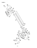
FIGURE 1

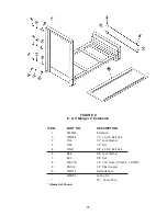
6’ & 9’ MERGER MAIN FRAME/POLE

Summary of Contents for M6

Page 1: ...CO INC P O BOX 768 715 387 3414 FAX 715 384 5463 MARSHFIELD WISCONSIN 54449 WARNING READ AND UNDERSTAND THIS MANUAL BEFORE OPERATING THIS EQUIPMENT UNSAFE OPERATION OR MAINTENANCE OF THIS EQUIPMENT C...

Page 2: ...e 14 15 Options 16 Ordering Parts About Improvements 17 Decal Location Identification 18 19 Figure 1 M6 M9 Merger Main Frame Pole 20 21 Figure 2 M6 M9 Merger Pick Up Head 22 23 Figure 3 M6 M9 Merger H...

Page 3: ...valuable information that should be passed on to the customer at the time this Mini Merger is delivered Check off each item as you explain it to the customer This pre delivery check list when properly...

Page 4: ......

Page 5: ...THE CAREFUL OPERATOR IS THE BEST OPERATOR MOST ACCIDENTS ARE CAUSED BY HUMAN ERROR CERTAIN PRECAUTIONS MUST BE OBSERVED TO PREVENT THE POSSIBILITY OF INJURY OR DAMAGE TRACTORS This operator s manual...

Page 6: ...d with the safety alert symbol DANGER identifies the most serious hazards Safety signs with signal word DANGER or WARNING are typically near specific hazards General precautions are listed on CAUTION...

Page 7: ...S AND WARNINGS AND W FUNCTION OF CONTROLS KEEP SAFETY DEVICES IN PLACE AND WORKING KEEP YOURSELF AND OTHERS WELL CLEAR OF PARTS PARTS P D POWER BEFORE SERVICING OR CLEANING THIS MACHINE 72203A DO NOT...

Page 8: ...ar the machine DO NOT ALLOW PERSONNEL OTHER THAN THE QUALIFIED OPERATOR NEAR THE MACHINE STAY CLEAR of machine when raising or lowering pickup Keep hands feet and clothing away from pickup and conveyo...

Page 9: ...Page 13 5 Check tires and inflate to recommended pressure 6 Run pickup and conveyor for several minutes to ensure proper assembly and lubrication Successful operation will be achieved by periodic adj...

Page 10: ...pick up into transport position Shown below is the valve in the locked and unlocked positions 10 Transport Position STAY CLEAR OF MOVING PARTS FAILURE TO HEED THIS WARNING MAY RESULT IN PERSONAL INJU...

Page 11: ...amage to Merger A PICKUP ADJUSTMENTS 1 Pickup belts are adjusted by adjusting the take up bolt B located on both ends of the pickup bottom roller The bearing bracket bolts C must be loosened before ad...

Page 12: ...never be closer than 3 4 from the ground When proper adjustment is obtained remove pin B and place in hole as close as possible below gauge wheel arm to support gauge wheel when raising head Excessiv...

Page 13: ...tractor throttle Coordinate speed of belts with ground speed of tractor To reverse direc tion of cross conveyor change hydraulic quick couplers at the cross conveyor drive motor C A flow of 16 GPM an...

Page 14: ...e seals indicating the correct amount of lubricant Wipe off excess grease to prevent accumu lation of grit around the bearings If equipped with accelerator oil roller chain daily Lubricate merger more...

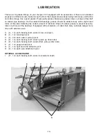
Page 15: ...15 LUBRICATION Continued B I Under Shield E G A C D F H A I Under Shield...

Page 16: ...16 OPTIONAL ACCELERATOR AND INVERTER ACCELERATOR INVERTER Remove accelerator for road transport Remove inverter for road transport Transport Position Working Position...

Page 17: ...not be ordered from illustration only Please order by complete part number 4 If your dealer has to order parts give shipping instructions VIA truck large pieces please specify local truck lines VIA Un...

Page 18: ...ividually by part num ber or by ordering a complete set ITEM PART NO DESCRIPTION A B12 2 H S Decal B 2 Red Reflective C 1494K 2 Warning Do Not Remove Shields D B6 4 H S Decal E 11599 2 Warning Do Not...

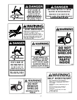
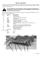
Page 19: ...DECAL LOCATION Continued A B L I K C Behind Shield Behind Shield A B 19 J D K I L C E G F...

Page 20: ...20 FIGURE 1...

Page 21: ...oll Pin 5 16 x 2 3 4 33 RG24 Bronze Washer 2 ID x 3 OD x 1 8 34 BFR527 Bronze Bushing 2 ID x 2 1 4 OD x 2 35 DWM59 Brake Bushing ITEM PART NO DESCRIPTION 6 HEAD 9 HEAD 36 WM286 Brake Band 37 WM210 Spr...

Page 22: ...22 FIGURE 2...

Page 23: ...30 SWM76 WM342 Front Roller 31 WM192 Left Front Roller Bracket 32 SWM31 DWM58 Poly Wind Guard ITEM PART NO DESCRIPTION 6 HEAD 9 HEAD 33 SWM9 DWM2 Wind Guard Holder 34 SWM32 DWM228 Wind Guard 35 DWM22...

Page 24: ...24 FIGURE 3...

Page 25: ...9 LW96 1 2 Street Tee 10 DF18 1 2 Check Valve 11 DF8 1 2 Tee 12 SWM22 Hose 1 2 x 216 SWM67 Hose 1 2 x 240 13 SWM24 Hose 1 4 x 180 SWM68 Hose 1 4 x 204 14 SWM25 Hose 1 4 x 190 SWM69 Hose 1 4 x 214 15...

Page 26: ...6 Plug In 2 DWM129 Yellow Hazard Lights 3 S310 Red Tail Lights 4 S308 Rubber Light Mount 5 SWM47 SWM70 Main Wire 6 SWM48 SWM71 2nd Wire 7 S317 Optional Tractor Cord Means Not Shown Means Same As Previ...

Page 27: ...PART NO DESCRIPTION 1 SWM50 Windrow Inverter Poly 2 SWM51 Windrow Inverter Frame 3 SWM52 Storage Mount NOTE Storage Mount Bolts onto SWM3 Caster Mount See Fig 1 FIGURE 5 6 9 MERGER OPTIONAL WINDROW I...

Page 28: ...28 FIGURE 6...

Page 29: ...Nut 10 DWM210 Latch Handle 11 DWM217 Latch 12 DWM218 Ready Rod 13 A14 3 8 Nylock Nut 14 DWM209 Mounting Bracket 2 15 X61 50 Connector Link 16 SWM53 50 Roller Chain 57 Pitch 17 X106 Sprocket 24T 1 Bor...

Page 30: ...Clevis Cap 2 23N143A Rod Cap 3 23N144 Piston 4 T134A Rod 5 BFR68 Cylinder Tube 6 T186 Tie Rod 7 23N148 Piston Nut 8 23N149 Plug 9 23N150A Rod Clevis 10 23N151 Seal Kit 11 BFR69A Complete Cylinder FIG...

Page 31: ...r 5 3 R35 1 2 Lock Washer 4 R29 1 2 Nut 5 12N51 3 8 x 2 3 4 Bolt Gr 5 6 B68 3 8 Lock Washer 7 K60 3 8 Nut 8 16SV141 1 2 x 24 Hose 1 2 MP 1 2 MPX 9 PB105 1 2 Pipe Coupler 10 WM214 Belt Extension WM220...

Page 32: ...SERVICE NOTES 32...

Page 33: ...this manual and apply this knowledge There is a right and a wrong way to do everything Please do not assume that you know how to operate and maintain your Mini Merger before reading this manual caref...

Page 34: ...H S MFG CO products approved for the FEMA SEAL OF QUALITY...

Reviews: