background image

MAIN APRON ADJUSTMENT

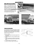
Tighten the two adjusting bolts on both 

sides (1 on each front corner of the  

spreader - see circled area in the pictures 

below) equally so that when properly     

tensioned, the apron chain on each side 

should sit 1/16” above the center driveshaft 

support cross member. 

The apron will be damaged if the machine 

is operated with one end of the apron slats 

running ahead of the opposite end.

ADJUSTMENTS

-23-

TIMING OF BEATERS

The vertical beaters on the manure spreader are preset  

from the factory. If it becomes necessary to service 

the beater assembly, the beaters must be timed so 

the flighting of the opposite beater is about halfway 

between the beater being timed. 

To time the beaters;

1.  Remove the top shield and bearing support from 

both beaters.

2. 

Lift/raise the beater up off of the gearbox splined 

shaft.

3. 

Rotate the beater so the flighting of the opposite 

beater is about halfway between the beater being 

timed. 

4.  Lower the beater on the splined shaft

5.  Replace the bearing support and top shield.

Summary of Contents for 6180

Page 1: ...85 Rev 00 HSMFG122122 Part 92785 Rev 00 HSMFG122122 READ AND UNDERSTAND THIS MANUAL BEFORE READ AND UNDERSTAND THIS MANUAL BEFORE OPERATING THIS EQUIPMENT UNSAFE OPERATION OPERATING THIS EQUIPMENT UNS...

Page 2: ...l 9 Explanation of Safety Signs 10 Safety Decals 11 13 Safety Information Warning Owner Must Read and Understand 14 Cap Screw Torque Values 15 Set Up Assembly 16 Transporting 17 Preparing for Operatio...

Page 3: ...y by their respective manufacturers H S reserves the right to request the return of any failed component This warranty in all its parts is extended solely to the original purchaser of the product is t...

Page 4: ...OF THIS WARRANTY H S and the companies affiliated with it make no warranties representations or promises express or implied as to the performance or freedom from defect of its products other than tho...

Page 5: ...3 Remove Copy At Perforation...

Page 6: ...4 Intentionally Left Blank...

Page 7: ...CORDS After the Manure Spreader has been completely set up check to be certain it is in correct operating order before delivering to the customer The following is a list of points to inspect Check off...

Page 8: ...Intentionally Left Blank 6...

Page 9: ...n operating this unit Explain recommended loads for different types of materials Explain to customer that regular lubrication is required for proper operation and long life of machine Show customer th...

Page 10: ...Intentionally Left Blank 8...

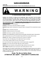
Page 11: ...EVER YOUR PERSONAL SAFETY IS INVOLVED TAKE TIME TO BE CAREFUL REMEMBER THE CAREFUL OPERATOR IS THE BEST OPERATOR MOST ACCIDENTS ARE CAUSED BY HUMAN ERROR CERTAIN PRECAUTIONS MUST BE OBSERVED TO PREVEN...

Page 12: ...n good condition Immediately replace any missing or damaged signs 10 OBSERVE MAXIMUM TRANSPORT SPEED The maximum transport speed for this implement is 32 km h 20 mph Some tractors are capable of opera...

Page 13: ...11 SAFETY DECALS...

Page 14: ...12 SAFETY DECALS...

Page 15: ...13 SAFETY DECALS...

Page 16: ...IED OPERATOR NEAR THE MACHINE Before starting tractor be sure PTO shields turn freely and PTO is securely locked to tractor DO NOT clean adjust or lubricate the machine when any part is in operation K...

Page 17: ...15...

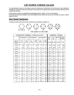
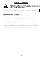
Page 18: ...ment and make sure that all bolts are tightened 4 Securely retighten after a few hours of operation as bolts can loosen up on new machinery 5 Lubricate the machine completely check the oil level of th...

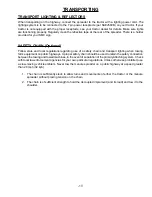
Page 19: ...garding use of a safety chain and transport lighting when towing farm equipment on public highways A proper safety chain should be used to retain the safety connection between the towing and towed mac...

Page 20: ...rsal joints of the power takeoff Secure the drawbar so that the hitch pin hole is directly below the power drive line TRACTOR CONNECTIONS 18 Hydraulics The spreader requires a 4 hose hook up 1 Connect...

Page 21: ...surfaces The shield surfaces must be kept dry as dirt accumulation on them will quickly cause these units to bind and not rotate Be sure that the rotating integral shields are not dented or damaged as...

Page 22: ...e cleaning or working on the spreader WINTER OPERATION In freezing weather make certain that the apron chain is not frozen to the floor or the hydraulic gate is not frozen to the track uprights or the...

Page 23: ...erse the main apron if a problem arises such as an obstruction in the beater area follow the steps below OPERATION CAUTION DO NOT RUN THE APRON CHAIN IN REVERSE LONGER THAN NECESSSARY AS DAMAGE COULDA...

Page 24: ...Disconnect Clutch located in the PTO driveline before the gearbox of the spreader Disconnect of the clutch during operation is normally due to large frozen chunks of manure foreign objects rocks chunk...

Page 25: ...TMENTS 23 TIMING OF BEATERS The vertical beaters on the manure spreader are preset from the factory If it becomes necessary to service the beater assembly the beaters must be timed so the flighting of...

Page 26: ...ront portion off of the PTO from the shaft 4 After removal of both PTO halves slide them together and store them in a safe place 5 Securely attach a lifting chain to the lifting eyes at the top of the...

Page 27: ...S The brake system is electric over hydraulic brake fluid only The controller must be located on the tractor for the brakes to operate If the tractor is set up with the 4 pin in the seven in plug as b...

Page 28: ...nd establish a systematic routine to ensure complete and quick lubrication of the machine PTO ASSEMBLY Keep the male and female driving elements well lubricated and free sliding Failure to observe thi...

Page 29: ...line PTO under rear of spreader 1 Zerk on each end of front idler shaft Remote Zerks Top LH Zerk Left Side Tandem Pivot Bottom LH Zerk Right Side Tandem Pivot Top Center Zerk Rear Drive Shaft Bearing...

Page 30: ...Do Not Remove Shields 1494L 1 Danger Rotating Driveline 1906C 2 Warning Stay Clear 1906F 6 Danger Keep Out 51010 4 Caution Pinch Point 71494A 1 Warning Do Not Remove Shields Only on Vertical Beater Sp...

Page 31: ...DECAL LOCATION 9194A 11599 82602 82602 29 1494L 9194A 12794 093366 093020...

Page 32: ...DECAL LOCATION 9194B 54033 30 1494A 94010 94013 86060 1494K 9194A 9194A 51010 51010 1494J 311 84044 1906F 72203A 1494K 9194A 96654 54045 DCAMB DCAMB...

Page 33: ...1906F 1906F DECAL LOCATION 31 093020 1494J DCAMB DCAMB DCAMB 86060 11599 11599 1906C 1906F 9194A 51010 94008 94011...

Page 34: ...DECAL LOCATION 32 DCAMB 1494J 86060 JD5922 DCRED 12794 71494A UNDER SHIELD 1906F 11599 11599 1906C JD5922...

Page 35: ...DECAL LOCATION 33 51010 1906F DCAMB 093020 DCAMB 9194A 94012 94009...

Page 36: ...r Hydraulics Insufficient Tractor Hydraulic Change Tractors Pressure TROUBLESHOOTING WARNING MAKE SURE THAT THE TRACTOR IS SHUT OFF AND THE SPREADER CANNOT MOVE BEFORE SERVICING THE MANURE SPREADER MA...

Page 37: ...____________________________ __________________________________________________ __________________________________________________ __________________________________________________ __________________...

Page 38: ...____________________________ __________________________________________________ __________________________________________________ __________________________________________________ __________________...

Page 39: ......

Page 40: ...Manufactured By H S MANUFACTURING CO INC 2608 S HUME AVE MARSHFIELD WI 54449 715 387 3414 hsmfgco com H S MFG CO products approved for the FEMA SEAL OF QUALITY...

Reviews: