Handler Red Wing 16B Operating Manual Download Page 4

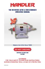
16B Red Wing Lathe & Chuk/Changer Instruction


CHUCK REMOVAL INSTRUCTIONS

Remove the lathe from the carton and place it in a suitable location on a sturdy horizontal surface.  
The unit must be bolted to the table top. Bolting the unit securely to a solid table top will prevent 
possible lathe movement during operation and possible operator injury.

Plug the lathe’s cord set into a grounded 115 Volt/60 Hz electrical socket only. Do not utilize a 
3-2 prong adapter. Failure to plug the lathe into a properly grounded receptacle may result in 
operator injury. Your lathe is now ready for operation with the aid of chucks placed on the shaft (see 
instructions).

The No. 26, 26A, 26L, and 28H lathes are constructed to function on two speeds. Low speed is  
1725 RPM and high speed is 3450 RPM. The lathe shaft is provided with special dental tapered 
shafts which will accept chucks which fit onto a tapered shaft only. The models 27, 29, & 29A are 
built to function at 3450 RPM. NOTE: if you have specified that your lathe should contain 1/2” straight 
shafts, only chucks which contain a 1/2” arbor hole will adapt to these shafts.

The polishing motor with a tapered shaft is provided with a left and right chuck remover (see figure 
No. 1). By pulling upward toward the front of the lathe, the chuck remover will unscrew outward to 
“push” the chuck from the tapered shaft. Various types of chucks and chuck accessories are utilized to 
perform different types of grinding and polishing operations with your lathe. These are attached to your 
lathe’s shaft via a friction fit.

TO PLACE A CHUCK ONTO THE SHAFT OF YOUR LATHE, PLEASE FOLLOW THESE INSTRUCTIONS:

1.  Make certain both the lathe’s shaft and the arbor hole of the chuck to be placed onto the shaft are  
 

clean of any dust and debris. Be certain the chuck remover on each side is in place.

2.  With the lathe turned “OFF”, place the chuck onto the right or left shaft of your lathe. DO NOT  
 

place a chuck labeled “R” or “L” on the opposite shaft. (See Instructions on following page.)

3.  Push the chuck onto the shaft as far as it will go. Since the chucks fit onto tapered shafts via  
 

friction fit, make certain the chuck is placed securely on the lathe shaft. It may be necessary to  


tap the end of the chuck onto the lathe shaft with the aid of a soft rubber, plastic or leather  


mallet. Do not use a metal hammer or mallet as this will damage the chuck.

4.   After the chuck has been placed securely on the lathe shaft, place the buff, brush, abrasive  
 

wheel, bur or mandrel onto the chuck. Secure this in place as per the manufacturers suggestions.

5.   Turn the lathe on and make certain the accessory which has been placed on the lathe chuck is  
 

securely in position. If either the chuck or accessory have not been secured to the lathe shaft,  


secure it now.

NOTE:  Many Red Wing polishing motors are shipped with 1/2” straight shafts.  Chucks used on Red 
Wing Polishing motors equipped with a 1/2” straight shaft utilize a set screw to hold the chuck in 
position.  Make certain to tighten this securely. 

FIGURE 1

PUSH ON AND TAP IN PLACE

CHUCK 

REMOVER

TURN MOTOR OFF

PULL HANDLE UPWARD TO REMOVE CHUCK

Summary of Contents for Red Wing 16B

Page 1: ...WARNING FOR YOUR SAFETY PLEASE READ INSTRUCTIONS BEFORE OPERATING TOOL WEAR EYE PROTECTION 16B RED WING LATHE CHUK CHANGER OPERATING MANUAL IMPORTANT INSTRUCTIONS 06 2009 FD 06 2009...

Page 2: ...which sustained damage detailing the possible damage and requesting they contact Handler Possible damage MUST BE CLAIMED by the receiver of the product not the sender RED WING MOTOR Your Red Wing has...

Page 3: ...AFETY READ INSTRUCTIONS BEFORE OPERATING TOOL WEAR EYE PROTECTION ALL ELECTRICAL ITEMS WITH A CORD SET Repair or Replace Damaged or worn cord Immediately Do not expose to rain or use in damp locations...

Page 4: ...d polishing operations with your lathe These are attached to your lathe s shaft via a friction fit To place a chuck onto the shaft of your lathe please follow these instructions 1 Make certain both th...

Page 5: ...pproximately 1 32 1 16 of an inch inward toward the lathe 5 Holding the Chuk Changer in your right hand move the activating handle clockwise to the 9 30 10 00 o clock position The Chuk Changer will mo...

Page 6: ...tightening set screw securely Scrape off all red paint that is on the 2 diameter housing 1 2 shaft File flat for set screw Remove if hub has plastic 1 32 maximum allowable shaft movement end play whe...

Page 7: ...dle is moved the clutch spring Part No 7 may be damaged or clutch spring tension may be released When clutch spring is damaged or tension released clutch will not engage properly See instructions unde...

Page 8: ...athe switch OFF and clutch handle straight down collets open unscrew otuer collet part No 5 with collet wrench Part No 8 Unscrew counter clockwise 2 Remove both inner and outer collets 3 Thoroughly cl...

Page 9: ...ge 4 A few chucks may require the chuck remover to be rotated 360 Degrees before the chuck accessory is removed Chucks fitted to polishing motors containing a 1 2 shaft are removed by loosening the se...

Page 10: ...r s automatic chucks are durable and built to save processing time and money 16 Chuk Changer The Handler Chuk Changer was designed to provide full automatic precision changing of 1 4 and 3 32 diameter...

Page 11: ...pecify L or R No 6 Thru Bold with nuts No 7 Bearings two per set for right and left side 1 and 2 speed lathes No 8 Rotor specify whether 1 or 2 speed lathe No 9 Centrifugal Switch specify whether 1 or...

Page 12: ...adjustable 6 x9 clear acrylic shield to help protect the polisher Hoods are available in 6 x8 and 10 widths Resin Hoods available in 6 width ONLY The protector was designed to provide protection from...

Page 13: ...Safety strap No 10RW Clutch complete for all Red Wing lathes No 10B Clutch complete for all Baldor lathes No 10RM Clutch complete with bearing for all Robbins Myers lathes No 10R Clutch complete with...

Page 14: ...y an agent of the carrier 5 In case of damage notify the delivering carrier IMMEDIATELY requesting that an inspection be made Retain a copy of the inspection request for claim purposes Failure to noti...

Page 15: ...ce 4 Store Idle Tools When not in use tools should be stored in dry high and locked location out of the reach of children 5 Don t Force Tool It will do the job better and be safe at the rate for which...

Page 16: ...talled operated and maintained in accordance with HANDLER procedures and recommendations During the life of this warranty HANDLER will repair or replace At HANDLER s option free of charge F O B its pl...

Reviews: