background image

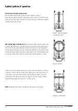
Figure 1. Wheels adjusted  
for forward motion

Figur 2. Rotation

Figure 3. Lateral travel

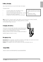
Battery charging 

Always charge the lift after use to ensure that the battery is fully charged. 

Charging procedure:

• 

Connect the charger cable to the batterypack, plug in  


the wall socket and switch on at plug socket.

• 

Check to ensure that the light on the charger lights up and that  


the battery’s power switch is switched on!

• 

Charging stops automatically when battery is fully charged.

NOTE! 

The lift must be charged for at least 10 hours before it is used for the first time. For maximum service life, 

charge batteries regularly. We recommend daily charging when the lift is used daily. 
Only the dedicated charger may be used.

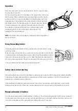
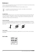
Emergency stop 


Emergency stop: 

Press the emergency-stop button on the EvaDrive cover. Emergency stop switches off all of the lift’s 

electrical functions. The battery scale continues to light continuously. 

Resetting: 

Turn the emergency-stop button in the direction of the arrows until the button pops out. 

Compatibility

EvaDrive is adapted for Eva450EE (60900002) and Eva600EE (60900003). 

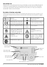
1. The green LED light confirms that the charger 

is connected to the power outlet and is receiving 

power. 

2. Red light indicates charging. 

3. Green light indicates full charge. 

Changing the battery

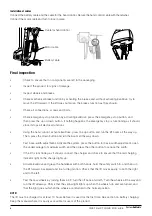
Loosen the two screws that holds the handlebar using an Allen key, and move  
up wards as far as possible. Remove the battery cable. Slide the battery off  
the rails on the on the backplate mounted on the mast.
Slide the new battery into the rails. reattach the handlebar and the battery cable. 

Handle the battery with care. Do not drop. 

TITLE

DATE

NAME

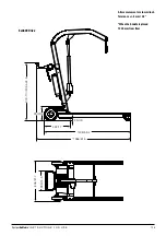
No burrs allowed

Break sharp edges: Rm

ax:0.3 mm / 0.3 mmx 4

5degrees

Replaces drawing/pa

rt number (Linido Part N

o)

Unless otherwise stated

, general tolerances ac

cording to ISO 2768-

Omitted dimensions a

ccording to

[9000_Eva 450 

Drive.dwg/step]

TITLE

DATE

NAME

No burrs allowed

Break sharp edges: Rmax:0.3 mm /

 0.3 mmx 45degrees

Replaces drawing/part number (Lin

ido Part No)

Unless otherwise stated, general to

lerances according to ISO 2768-

Omitted dimensions according to

[9000_Eva 450 Drive.dwg/

step]

TITLE

DATE

NAME

No burrs allowed

Break sharp edges: Rm

ax:0.3 mm / 0.3 mmx 4

5degrees

Replaces drawing/pa

rt number (Linido Part N

o)

Unless otherwise stated

, general tolerances a

ccording to ISO 2768-

Omitted dimensions a

ccording to

[9000_Eva 450 

Drive.dwg/step]

13

I N S T R U C T I O N S   F O R   U S E

System

RoMedic

TM

English

Summary of Contents for SystemRoMedic EvaDrive

Page 1: ...oMedic TM Instructions for use English Bruksanvisning Svenska Brukermanual Norsk Brugsvejledning Dansk K ytt ohje Suomi Gebrauchsanweisung Deutsch Handleiding Nederlands Manuel utilisateur Fran ais Ma...

Page 2: ...driving function in all directions Check that the accessory EvaDrive is properly mounted on the lift Always read the user manuals for all assistive devices used during a transfer Keep the user manual...

Page 3: ...0 mm Installation of the handlebar The handlebar must be installed on the mast at a height of at least 33 4 inch from the floor Measure from the lowest point of the handlebar The handlebar is secured...

Page 4: ...press the down button and run the boom all the way down Test base width adjustment Activate the system press the button for base width adjustment open the undercarriage to maximum width and then pres...

Page 5: ...tions are made by authorized personnel Never attempt to lift the mobile lift unit by the handlebar Ensure that there are no obstacles or people in the way of the lift Never stand on the lift during op...

Page 6: ...unction is described in the respective section in the user manual or in the user manual for the respective accessory Below is a brief description of the functions that are available for caregivers and...

Page 7: ...level Solid light indicates battery capacity remaining Blinking light indicates error A service technician can determine the source of the error Power button Press lightly to activate EvaDrive Wait ab...

Page 8: ...eration of the lift is not possible until EvaDrive has completed automatic calibration If the handlebar is hit violently or subjected to impact the sensors neutral values can be affected so much that...

Page 9: ...top blinking All or parts of the battery scale blink quickly Something is wrong with the lift s electrical system Restart EvaDrive If there is still a problem contact Handicare Red light battery scale...

Page 10: ...ned see Fig 2 The yellow LED light on the control panel indicates that the wheels are in the turned position Grasp the handlebar and hold in the safety switch then turn the lift in the desired directi...

Page 11: ...rive cover Emergency stop switches off all of the lift s electrical functions The battery scale continues to light continuously Resetting Turn the emergency stop button in the direction of the arrows...

Page 12: ...ge the aluminium and the plastic materials If disinfection is needed 70 ethanol 45 isopropanol or similar should be used Disinfect the parts that come in contact with a user before the lift is used fo...

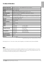
Page 13: ...ght Eva450Drive 127 87 lbs 58 kg Eva600Drive 141 1 lbs 64 kg Weight heaviest part Eva450Drive 97 lbs 44 kg Eva600Drive 110 2 lbs 50 kg Turning diameter Eva450Drive 54 inch 1340 mm Eva600Drive 61 8 inc...

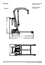
Page 14: ...All measurement are in mm inch Tolerance 5 mm 0 2 When the handle is placed 1000 mm from floor Eva450Drive 25 0 9 427 16 8 1307 51 4 1450 57 1 240 9 4 900 1100 35 4 43 3 124 I N S T R U C T I O N S F...

Page 15: ...n mm inch Tolerance 5 mm 0 2 Eva600Drive When the handle is placed 1000 mm from floor 806 31 7 395 15 5 25 0 9 432 17 1408 55 4 1566 61 6 240 9 4 900 1100 35 4 43 3 125 I N S T R U C T I O N S F O R U...

Page 16: ...es RF energy only for its internal function Therefore its RF emissions are very low and are not likely to cause any interference in nearby electronic equipment RF emissions CISPR 11 Class A The EvaDri...

Page 17: ...e 2 kV for common mode Mains power quality should be that of a typical commercial or hospital environment Voltage dips short interruptions and voltage variations on power supply input lines IEC 61000...

Page 18: ...occur in the vicinity of equipment marked with the following symbol NOTE 1 At 80MHz and 800MHz the higher frequency range applies NOTE 2 These guidelines may not apply in all situations Electromagnet...

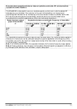
Page 19: ...ncy of transmitter m 150 kHz to 80 MHz P d 2 1 80 MHz to 800 MHz P d 2 1 800 MHz to 2 5 GHz P d 3 2 0 01 0 12 0 12 0 24 0 1 0 38 0 38 0 73 1 1 2 1 2 2 3 10 3 8 3 8 7 3 100 12 12 23 For transmitters ra...

Page 20: ...oMedic offers improvement of both work environment and quality of care and at the same time achieves significant cost savings Always make sure that you have the correct version of the manual The most...

Reviews: