background image

6

Installation

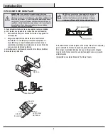
MOUNTING OPTIONS

WARNING:

 To reduce the risk of fire, electric shock 

or personal injury, mount to outlet box marked 

“Acceptable for fan support of 35lbs. (15.9 Kg) or less”, 

and use screws provided with the outlet box. An outlet 

box commonly used for the support of lighting fixtures 

may not be acceptable for fan support and may need to 

be replaced. If in doubt, consult a qualified electrician.

If your ceiling fan does not have an existing UL-listed mounting 

box, then install one using the following instructions:


Disconnect the power by removing the fuses or turning off 

the circuit breakers.


Secure the outlet box directly to the building structure. Use 

the appropriate fasteners and materials. The outlet box and 

its bracing must be able to fully support the weight of the 

moving fan (at least 35 lbs.). Do not use a plastic outlet box.

The illustrations below show three different ways to mount the 

outlet box.

If the canopy touches the downrod, then remove the canopy bottom 
cover, and turn the canopy 180° before attaching the canopy to the 
mounting plate.
To hang your fan where there is an existing fixture but no ceiling joist, 
you may need an installation hanger bar as shown above
(available at any Home Depot store).

NOTE:

 You may need a longer downrod to maintain 

proper blade clearance when installing on a steep, sloped 

ceiling. The maximum angle allowable is 30° away from 

horizontal.

Outlet Box

Outlet Box

Recessed

Outlet

Box

Provide Strong

Support

Ceiling

Mounting

Plate

Outlet Box

Hanger Bar

Summary of Contents for WELLSTON EF200B-44

Page 1: ...Service 8 a m 6 p m EST Monday Friday 1 877 527 0313 HAMPTONBAY COM THANK YOU We appreciate the trust and confidence you have placed in Hampton Bay through the purchase of this ceiling fan We strive...

Page 2: ...ter making electrical connections spliced conductors should be turned upward and pushed carefully up into the outlet box The wires should be spread apart with the grounded conductor and the equipment...

Page 3: ...shall render the warranty invalid There is no other express warranty Hampton Bay hereby disclaims any and all warranties including but not limited to those of merchantability and fitness for a partic...

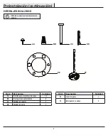
Page 4: ...tachment screws 15 BB Wire connecting nut 3 CC Hanger pin 1 DD Locking pin 1 Part Description Quantity EE Rubber Gasket 1 FF Pull chain 2 Pre Installation continued HARDWARE INCLUDED NOTE Hardware not...

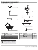
Page 5: ...motor assembly 1 Part Description Quantity E Light kit fitter assembly 1 F Blade 5 G Blade bracket 5 H Glass bowl 1 I CFL bulb 14 watts maximum 2 IMPORTANT This product and or components are governed...

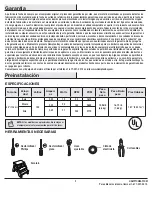
Page 6: ...ructure Use the appropriate fasteners and materials The outlet box and its bracing must be able to fully support the weight of the moving fan at least 35 lbs Do not use a plastic outlet box The illust...

Page 7: ...near the end of the hanger pin CC until it snaps into its locked position Re tighten the 2 setscrews PP on the collar on top of the motor housing D Remove the mounting plate A from the canopy C by lo...

Page 8: ...let box marked Acceptable for fan support of 35lbs 15 9 Kg or less and use screws provided with the outlet box A II II Close to Ceiling Mounting Routing the wires 1 2 Remove the mounting bracket A fro...

Page 9: ...ng mounting bracket and one from the ball downrod assembly When using close to ceiling mount ing there is only one green grounding lead from the ceiling mounting bracket sine the ball downrod assembly...

Page 10: ...remaining two mounting screws WW into the holes in the canopy C and tighten firmly 4 WARNING When using the standard ball downrod mounting the tab in the ring at the bottom of the mounting bracket mus...

Page 11: ...assembly With power off install the two bulbs I by twisting them into the light bulb sockets Position the glass bowl H over the threaded nipple and pass the pull chain for the fan through the hole und...

Page 12: ...The slide switch controls the direction of the blades forward switch down or reverse switch up Warm weather Forward A downward airflow creates a cooling effect This allows you to set your air conditio...

Page 13: ...the ceiling above the tip of one of the blades Measure from a point on the center of each blade to the point on the ceiling Measure this distance Rotate the fan until the next blade is positioned for...

Page 14: ...Questions problems missing parts Before returning to the store call Hampton Bay Customer Service 8 a m 6 p m EST Monday Friday 1 877 527 0313 HAMPTONBAY COM Retain this manual for future use...

Page 15: ...e Hampton Bay de lunes a viernes entre 8 a m y 6 p m hora del Este de EE UU 1 877 527 0313 HAMPTONBAY COM GRACIAS POR TU COMPRA Apreciamos la confianza que has depositado en Hampton Bay al comprar est...

Page 16: ...xiones el ctricas debes voltear los conductores empalmados hacia arriba y empujarlos con cuidado hacia dentro de la caja el ctrica Los cables deben estar separados con el cable a tierra y el conductor...

Page 17: ...autorizadas anular la garant a No hay ninguna otra garant a expresa Mediante la presente Hampton Bay se exime de cualquier garant a incluyendo pero sin limitarse a aquellas de comercial izaci n e ido...

Page 18: ...BB Tuerca para conectar cables 3 CC Pasador de soporte 1 DD Pasador de cierre 1 Pieza Descripci n Cantidad EE Junta de goma 1 FF Interruptor de cadena 2 Preinstalaci n continuaci n HERRAJES INCLUIDOS...

Page 19: ...tilador 1 Pieza Descripci n Cantidad E Ensamblaje del soporte del kit de luces 1 F Aspa 5 G Soporte de aspa 5 H Taz n de vidrio 1 I Bombilla CFL m ximo de 14 Watts 2 IMPORTANTE Este producto y o sus c...

Page 20: ...a la estructura del edificio Usa sujetadores y materiales apropiados La caja el ctrica y su soporte deben poder sostener el peso completo del ventilador en movimiento al menos 35 lb No uses una caja e...

Page 21: ...cio cercano al extremo del pasador de soporte CC hasta que quede encajado en su posici n Vuelve a ajustar los tornillos PP del collar n en la parte superior de la carcasa del motor D Retira la placa d...

Page 22: ...como aprobada como soporte de ventiladores de 35 lb 15 9 kg o menos y usa los tornillos de montaje que vienen con la misma A II II Montaje Cerca del Techo Disposici n de los cables 1 2 Retira el sopor...

Page 23: ...desde el soporte de montaje de techo y otro desde el ensamblaje del tubo bajante bola Cuando uses el montaje cerca del techo habr solamente un cable a tierra verde del soporte de montaje de techo esto...

Page 24: ...tantes WW en los orificios de la cubierta C y aprieta firmemente 4 ADVERTENCIA Cuando uses el montaje del tubo bajante bola est ndar la pesta a en el aro en la parte inferior del soporte de montaje de...

Page 25: ...enrosc ndolas en los portabombillas Coloca el taz n de vidrio H sobre la boquilla enroscada y pasa la cadena del interruptor del ventilador a trav s del orificio gu a en el lado del ensamblaje del ki...

Page 26: ...ventiladores Los controles del interruptor deslizante cambian la direcci n de las aspas hacia delante interruptor para abajo o reversa interruptor para arriba Clima c lido Hacia adelante Un flujo de...

Page 27: ...eben a que las aspas no est n a un mismo nivel Verifica este nivel seleccionando un punto en el techo sobre la punta de una de las aspas Mide desde un punto en el centro de cada aspa al punto en el te...

Page 28: ...iezas faltantes Antes de regresar a la tienda llama al Servicio al Cliente de Hampton Bay de Lunes a Viernes entre 8 a m y 6 p m hora del Este de EE UU 1 877 527 0313 HAMPTONBAY COM Conserva este manu...

Reviews: