HAMPTON BAY Greenfire GC60 Technical Manual Download Page 10

hot enough to cause burns if touched by children. Non-combustible shielding or guards may be required.

3.  Termination must exhaust above the inlet elevation. It is recommended that at least five feet of vertical pipe be 

installed outside when the appliance is vented directly through a wall, to create some natural draft to prevent the 

possibility of smoke or odor during appliance shut down or power failure. This will keep exhaust from causing a 

nuisance or hazard from exposing people or shrubs to high temperatures. In any case, the safest and preferred 

venting method is to extend the vent through the roof vertically.

4. Distance from the bottom of the termination and grade is 12” (30 cm) minimum. This is conditional upon the 

plants and nature of grade surface. The exhaust gases are hot enough to ignite grass, plants and shrubs located 

in the vicinity of termination. The grade surface must not be lawn.

5. If the unit is incorrectly vented or the air to fuel mixture is out of balance, a slight discoloration of the exterior 

of the house might occur. Since these factors are beyond the control of Regency Fireplace Products, we grant no 

guarantee against such incidents.

6.  Horizontal terminations must extend at least 12” (30 cm) away from the building.

NOTE: Venting terminals shall not be recessed into walls or siding.

Installation

V

ENT

 T

ERMINATION

 R

EQUIREMENTS

:

IT IS RECOMMENDED THAT YOUR PELLET STOVE BE INSTALLED BY AN AUTHORIZED DEALER/INSTALLER. 

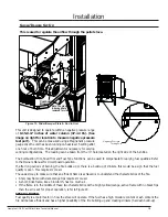
Figure 6: Use in conjunction with Table 2 for allowable exterior vent termination 

locations. 

Table 2: Use in conjunction with Figure 6 for allowable exterior vent termination locations. 

Letter

Minimum Clearance

Description

A

24 in (61 cm)

Above grass, top of plants, wood, or any other combustible materials.

B

48 in  (122 cm) 

Beside/below any door or window that may be opened. (18” (46 cm) if outside 

fresh air installed.) 

C

12 in (30 cm)

Above any door or window that may be opened. (9” (23 cm) if outside fresh air 

installed.) 

D

24 in (61 cm)

To any adjacent building, fences and protruding parts of the structure.

E

24 in (61 cm)

Below any eave or roof overhang

F

12 in (30 cm)

To outside corner.

G

12 in (30 cm)

To inside corner, combustible wall (vertical and horizontal terminations).

H

3 ft (91 cm) within a height 

of 15 ft (4.5 m) above the 

meter/regulator assembly

To each side of center line extended above natural gas or propane meter/

regulator assembly or mechanical vent.

I

3 ft (91 cm)

From any forced air intake of other appliance

J

12 in (30 cm)

Clearance to non-mechanical air supply inlet to building, or the combustion air 

inlet to any appliance.

K

24 in (61 cm)

Clearance above roof line for vertical terminations.

L

7 ft (2.13 m)

Clearance above paved sidewalk or paved driveway located on public property.

Air Supply Inlet

Gas Meter

Restriction Zone

(Termination not allowed)

Termination Cap

G

G

Opens

Opens

Opens

D

F

B

B

A

I

H

K

G

G

L

C

E

1. 

Do not terminate the 

vent in any enclosed or 

semi-enclosed areas such 

as a carport, garage, 

attic, crawlspace, narrow 

walkway, closely fenced 

area, under a sundeck 

or porch, or any location 

that can build up a 

concentration of fumes 

such as stairwells, covered 

breezeway, etc.

2. Vent surfaces can become 

Hampton GC60 Cast Pellet Stove Technical Manual

10

Summary of Contents for Greenfire GC60

Page 1: ...a V4G 1H4 GC60 080 02 17 14 GC60 WARNING Improper installation adjustment alteration service or maintenance can cause injury property damage or loss of life Refer to this manual For assistance or addi...

Page 2: ...result For your safety follow the installation instructions contact local building fire officials or authority having jurisdiction about restrictions and installation inspection requirements in your a...

Page 3: ...Locations 11 Mobile Home Installation 12 Corner Through Wall Installation 12 Horizontal Exhaust Through Wall Installation 13 RECOMMENDED Through Wall With Vertical Rise and Horizontal Termination Ins...

Page 4: ...ed to clean to be safe OPERATION The door and ash drawer must be kept closed when the unit is in operation to prevent fume spillage and for proper and safe operation of the pellet stove Also ensure al...

Page 5: ...uction doesn t meet load capacity suitable measures e g load distributing plate must be taken to achieve it DO NOT INSTALL A FLUE DAMPER IN THE EXHAUST VENTING SYSTEM OF THIS UNIT DO NOT CONNECT THIS...

Page 6: ...of floor protection in front of and to the sides of the door opening Serial No No De Seri To Start Stove Select fuel type mode PREMIUM PELLETS for superior quality pellet fuel REGULAR PELLETS for all...

Page 7: ...ellet Heater 6mm dia Pellets wood corn wheat barley Voltage Current Max Power 110 120 V 4 2 Amps 504 Watts Frequency Hopper Capacity Consumption on Low 60 Hz up to 60 lb 36 3 Kg 1 5 lb hr 0 68 Kg hr T...

Page 8: ...y onto carpet If it is to be installed on a carpeted area a solid surface wood metal or approved hearth pad must be installed between the unit and the carpet 6 This unit uses large quantities of air f...

Page 9: ...the sides of the door opening Figure 4 GC60 Clearance to Combustibles THERMOSTAT INSTALLATION 1 Install the wall thermostat millivolt rated thermostat recommended or a 12 24 Volt rated thermostat set...

Page 10: ...xterior vent termination locations Table 2 Use in conjunction with Figure 6 for allowable exterior vent termination locations Letter Minimum Clearance Description A 24 in 61 cm Above grass top of plan...

Page 11: ...rtight homes and mobile homes When connecting to an outside fresh air source do not use plastic or combustible pipe A 3 minimum 76 mm ID inside diameter steel aluminum or copper pipe or ducting should...

Page 12: ...ectrically grounded to the chassis of your home permanently Do not install in a room people sleep in Outside fresh air is mandatory Secure outside air connections directly to fresh air intake pipe and...

Page 13: ...ned with at least three 3 screws 1 Place the appliance 15 37 5 cm away from the wall If the stove will be installed on a hearth pad set the unit on it 2 Locate the center of the exhaust pipe on the st...

Page 14: ...152 cm of vertical pipe in the system to help naturally draft the unit in the event of extreme weather or a power outage Some horizontal through wall installations may require a T and 3 to 5 feet 91...

Page 15: ...r thimble 4 90 Elbow Vertical section of 4 pipe Wall Thimble 4 45 Elbow with screen or Termination Cap Installation to use if there is a concrete or retaining wall in line with exhaust vent on pellet...

Page 16: ...INSTALLATIONS section and then finish it by performing the following refer to Figure 15 1 Install a tee with clean out on the outside of the house 2 Install PL vent upward from the tee Make sure that...

Page 17: ...installed vertically it will meet the minimum clearance from a combustible wall stated by the vent manufacturer 2 Install the tee with clean out 3 Install the pellet vent upward from tee When you reac...

Page 18: ...xist fresh air intake can be taken through back of the fireplace or through the ash dump Installation HEARTH MOUNT INSTALLATION Figure 17 Hearth Mount Side View Figure 18 Hearth Mount Over View 1 Lock...

Page 19: ...ype Functions can be used to compensate for varying fuel qualities Refer to the Owners Manual for circuit board operation If after long periods of burning the fire builds up or there is a build up of...

Page 20: ...ng unit may be out of fuel Check the Door and Ash Pan door THEY MUST BE CLOSED TIGHT See section 8 The Fuel will not light Check the fuse on the circuit board If the unit still does not start contact...

Page 21: ...e termination into a low pressure zone To reset Circuit Board after a trouble code push the ON OFF button 5 Unit is on but auger motor does not turn at all Check the line fuse to see if it has blown C...

Page 22: ...es out and leaves fresh unburned fuel in the burn pot liner the fire is going out before the stove shuts off Trim the combustion air down to decrease the magnahelic pressure Turn the Heat Level up sli...

Page 23: ...ge White Grey Grey White Blue Yellow Auger Motor White Yellow Vacuum Switch Connect Thermostat Here Brown Brown Blue Purple Yellow Red Thermostat Combustion Blower Black Black White Green Ground 120V...

Page 24: ...t shown LATCH BOLT ROLLERS C W NUT GC60 031 not shown 2 AMP SMALL FUSE GC60 032 not shown 4 AMP SMALL FUSE IGNITOR GC60 033 not shown ADJ AUGER FEED COVER KIT N C PRE NOV 2010 GC60 034 not shown COMBU...

Page 25: ...FIREBOX LOWER GC60 045 31 GC60 CONTROL PANEL WITH DECAL GC60 055 32 DAUGHTER BOARD GC60 022 33 MOTHER BOARD GC60 023 39 ASH PAN GC60 046 40 GLASS GC60 024 42 DOOR COMPLETE GC60 026 43 AUGER TUBE COVER...

Page 26: ...arts Diagram Components 26 22 48 19 54 1 52 55 2 53 23 25 10 44 32 33 11 24 4 9 6 3 12 21 20 40 50 31 39 42 47 15 8 7 49 56 43 51 5 14 16 27 46 17 45 Hampton GC60 Cast Pellet Stove Technical Manual 26...

Page 27: ...COAL GC60 221 60 GC60 CAST LEG CHARCOAL GC60 231 61 GC60 CAST SIDE LEFT CHARCOAL GC60 241 62 GC60 CAST SIDE RIGHT CHARCOAL GC60 251 63 GC60 CAST LEG LIP LEFT CHARCOAL GC60 261 64 GC60 CAST LEG LIP RIG...

Page 28: ...efects in materials and workmanship for part repair or replacement for the first three 3 years and limited labour for the first two 2 years to the original purchaser Please see the exclusions and limi...

Page 29: ...zed Hampton dealer before installation 10 FPI will not be responsible for inadequate performance caused by environmental conditions or use of any fuel other than certified wood pellets 11 The Limited...

Page 30: ...to replace or repair items under this Limited Warranty will be covered per our warranty service fee reimbursement schedule Labour rates are set per component and as such total labour costs may not be...

Page 31: ...__________________ ___________________________________________________ ___________________________________________________ ___________________________________________________ _________________________...

Page 32: ..._______ Installer ___________________________________________________________ Phone ___________________________________________________________ Date Installed _________________________________________...

Reviews: