background image


M

O

C

.

Y

A

B

N

O

T

P

M

A

H


5


 .

e

c

n

a

t

s

i

s

s

a

 r

e

h

t

r

u

r

o

3

1

3

0

-

7

2

5

-

7

7

8

-

1

 t

c

a

t

n

o

c


e

s

a

e

l

P


Pre-Installation (continued)  

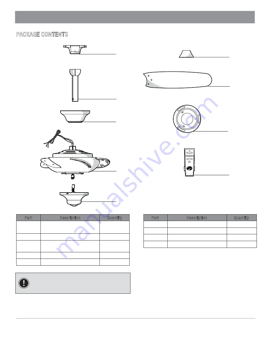
PACKAGE CONTENTS 


Part 

Description 

Quantity

A


Slide-on mounting bracket 

(inside the canopy) 

1

Ball/downrod assembly 

1

C

Canopy with canopy ring 

attached 

1

Fan-motor assembly 

1

E

Part

Description 

Quantity

F

Decorative motor collar cover

1

G

Blade

H

Switch cup adaptor

I

IMPORTANT:

 This product and/or components are 

governed by one or more of the following U.S. Patents: 
5,947,436; 5,988,580; 6,010,110; 6,046,416, 6,210,117 and 
other patents pending.


A

B

F

Remote control (battery included)

1
1

5

Switch cup (receiver included)

1

D

B

B

G

H

I

E

Summary of Contents for Altura

Page 1: ...ance your home Visit us online to see our full line of products available for your home improvement needs Thank you for choosing Hampton Bay USE AND CARE GUIDE ALTURA 68 INCH CEILING FAN Questions pro...

Page 2: ...carefully up into the outlet box The wires should be spread apart with the grounded conductor and the equipment grounding conductor on one side of the outlet box 8 All setscrews must be checked and r...

Page 3: ...ranty invalid There is no other express warranty Hampton Bay hereby disclaims any and all warranties including but not limited to those of merchantability and fitness for a particular purpose to the e...

Page 4: ...ED NOTE Hardware not shown to actual size Part Description Quantity AA Blade attachment hardware 16 BB Plastic wire connector 3 CC Hanger pin 1 DD Locking pin 1 Part Description Quantity EE Balancing...

Page 5: ...l downrod assembly 1 C Canopy with canopy ring attached 1 D Fan motor assembly 1 E Part Description Quantity F Decorative motor collar cover 1 G Blade H Switch cup adaptor I IMPORTANT This product and...

Page 6: ...he appropriate fasteners and materials The outlet box and its bracing must be able to fully support the weight of the moving fan at least 50 lbs Do not use a plastic outlet box The illustrations below...

Page 7: ...C Make sure the slot openings are on top and route the wires through the canopy C and then through the ball downrod assembly B 3 Assembling the fan Loosen but do not remove the setsrew GG on the coll...

Page 8: ...ounting bracket A over the two screws provided with the outlet box If necessary use leveling washers not included between the mounting bracket A bracket A is toward the outlet box Securely tighten the...

Page 9: ...n the other side Turn the wire connecting nuts upward and push the wiring into the outlet box MM WARNING Each wire nut supplied with this fan is designed to accept up to one 12 guage house wire and tw...

Page 10: ...ng the decorative nuts FF and the blade attachment screws AA as shown Start a blade attachment screw AA into the decorative nut FF Repeat for the two remaining decorative nuts and blade attachment scr...

Page 11: ...n the narrow end of the keyholes Re install the one screw that was removed in first step Tighten all three screws firmly Remove one screw from the switch cup adaptor H Loosen but do not remove the oth...

Page 12: ...receivers Make sure no other receivers are operating during the learning process Separate the fan power switches by approximately 2 meters Remote control operation NOTE This remote is equipped with 1...

Page 13: ...with a lacquer to minimize discoloration or tarnishing You can apply a light coat of furniture polish to the wood for additional protection and enhanced beauty Cover small scratches with a light appli...

Page 14: ...g this time If you are using the Ceiling Fan light kit ensure the screws securing the glassware are tight Check that the light bulbs are also secure Ensure the canopy is a short distance from the ceil...

Page 15: ...M O C Y A B N O T P M A H 5 1 e c n a t s i s s a r e h t r u f r o f 3 1 3 0 7 2 5 7 7 8 1 t c a t n o c e s a e l P This page intentionally left blank...

Page 16: ...estions problems missing parts Before returning to the store call Hampton Bay Customer Service 8 a m 6 p m EST Monday Friday 1 877 527 0313 HAMPTONBAY COM Retain this manual for future use X0000000000...

Page 17: ...ompleta de productos disponibles para las necesidades de mejoras de tu hogar Gracias por elegir Hampton Bay GU A DE USO Y MANTENIMIENTO VENTILADOR DE TECHO DE 68 PLG 1 72 M Preguntas problemas o pieza...

Page 18: ...deben estar separados con el cable a tierra y el conductor a tierra del equipo hacia uno de los lados de la caja el ctrica 8 Todos los tornillos colocados se deben verificar y ajustar donde sea necesa...

Page 19: ...otra garant a expresa Mediante la presente Hampton Bay se exime de cualquier garant a incluyendo pero sin limitarse a aquellas de comercializaci n e idoneidad para un fin particular de acuerdo a lo co...

Page 20: ...o real de los herrajes Pieza Descripci n Cantidad Pieza Descripci n Cantidad AA Herrajes para montaje de las aspas Conector pl stico para cable Pasador de soporte Pasador de cierre 16 Kit de compensa...

Page 21: ...C Cubierta con aro incorporado Ensamblaje del motor del ventilador 1 1 D E F 1 G H Adaptador de la caja del interruptor Cubierta decorativa del collar n del motor Aspa I IMPORTANTE Este producto y o...

Page 22: ...riales apropiados La caja el ctrica y su soporte deben sostener el peso completo del ventilador en movimiento al menos 50 lb No uses una caja el ctrica de pl stico Las ilustraciones a continuaci n mue...

Page 23: ...de la cubierta C y luego a trav s del ensamblaje del tubo bajante bola B 3 C mo ensamblar el ventilador Afloja sin quitar los tornillos GG del collar n ubicados en la parte superior de la carcasa de...

Page 24: ...de montaje A sobre los dos tornillos suministrados con la caja el ctrica Si es necesario usa arandelas niveladoras no incluidas entre el soporte de montaje A y la caja el ctrica F jate que el lado pl...

Page 25: ...ca el cableado dentro de la caja el ctrica MM ADVERTENCIA Cuando uses el montaje de tubo bajante y bola est ndar la pesta a en el aro en la parte inferior del soporte de montaje debe encajar en la ran...

Page 26: ...vas FF y los tornillos para montar las aspas AA como se muestra Monta un tornillo para montar las aspas AA en la tuerca decorativa FF Repite el proceso para las dos tuercas decorativas restantes y los...

Page 27: ...instala el tornillo de montaje que retiraste en el paso 1 Aprieta firmemente los tres tornillos Quita un tornillo del adaptador de la caja del interruptor H Afloja pero no quites los otros dos tornill...

Page 28: ...roceso de memorizaci n Separa los interruptores de corriente del ventilador aproximadamente a 2 metros Operaci n por control remoto NOTA Este control remoto est equipado con 16 combinaciones de c digo...

Page 29: ...s a la madera para una mayor protecci n y belleza Cubre los ara azos peque os con una leve aplicaci n de lustrador para calzado Tu ventilador no necesita lubricaci n El motor tiene cojinetes de bola s...

Page 30: ...en en ese per odo Si usas el kit de luces de Ventilador de Techo aseg rate de que los tornillos que sujetan el vidrio est n bien colocados Verifica que las bombillas de luz est bien aseguradas Aseg ra...

Page 31: ...HAMPTONBAY COM 5 1 Para obtener asistencia llama al 1 877 527 0313 Esta p gina se ha dejado en blanco a prop sito...

Page 32: ...faltantes Antes de volver a la tienda llama al Servicio al Cliente de Hampton Bay de lunes a viernes de 8 a m a 6 p m Hora Est ndar del Este 1 877 527 0313 HAMPTONBAY COM Conserva este manual para us...

Reviews: