


Special Performance Features
13
t
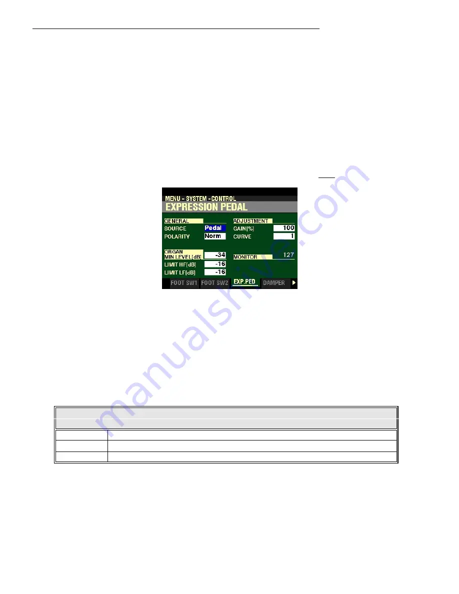
EXPRESSION PEDAL
This FUNCTION Mode Menu allows you to control how a connected Expression Pedal will function.
From the screen shown on the previous page, press the PAGE “
u
” button once.
The box to the right of “SOURCE” should be highlighted.
You are now in the portion of the CONTROL Edit Menu which pertains to Expression settings.
The following pages will explain how to set the Expression parameters to your preference.
SOURCE
This Parameter allows you to select the source of expression control. The data chart below shows the
options you may select.
EXPRESSION SOURCE Settings
Parameter
Description
Exp. Pedal
Instrument volume is controlled by a connected Expression Pedal.
MIDI
MIDI Expression Data (CC#11) will be received at the UPPER Internal Channel
Both
A connected Expression Pedal will control both instrument volume and MIDI Expression data.
Turn the VALUE knob to make your selection.


