Hamilton Air 5000 Series Installation & Service Manual Download Page 20

20 

08-315 (3/6/12)

Connect the supplied 12VDC power supply to the 
power socket on the back of the stand and plug it into 
a 110VAC outlet. If a different power supply must be 
used for some reason, it must be rated for at least 2A. 
The center conductor of the 2.1mm barrel connector is 
positive. 

Do not power this unit using the power 

distribution board which was previously used with the 
older B5450 unit.

 The 5550 requires approximately 

1.5A of current per unit.

Operation

Turn on power to the video head using the toggle switch on the lower left of the stand. 
Adjust the height of the video head as necessary by first loosening the adjustment knob on the back 
of the stand. Tighten the knob when the desired height is achieved. Note that there are two holes in 
the back of the stand for the adjustment knob. Using the top hole the height can be adjusted between 
approximately 14.5”-19”. Using the bottom hole the height can be adjusted between approximately 
14.5”-16”. The bottom hole also allows for a greater upward tilt angle at the lowest height allowing 
the video unit to be placed under a hanging pneumatic terminal if desired.
Tilt the video head up by grasping the sides of the unit. The tilt latch bracket will lock the video head 
into place in steps. Tilt the head back down by first slightly tilting further up to release pressure on 
the tilt latch bracket and then pulling the handle of the bracket forward allowing the video head to 
drop down. Note that there are two holes in the top of the tilt latch bracket. Mounting the bracket 
using the opposite hole will allow the tilt angle to change slightly at each latch position.
Use the lever beside the camera opening to tilt the camera up or down.

Service Adjustments

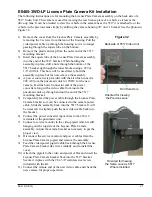
Service adjustments require access to the inside of the video head. Remove the 6 screws from the 
back side and remove the front cover.
Place the unit in “service” mode by placing the service switch at the upper left of the video head to 
the rear position. This will connect the camera directly to the monitor. 

(The service switch does not 

exist on the 5550-1.)

The camera has been focused at the factory and no further adjustment should be necessary. If 
focusing is required, loosen the small set screw and then rotate the lens to the desired focus. Snug 
the set screw when finished but do not over tighten to avoid creating a dimple in the lens threads 
making future fine adjustments difficult.
The monitor is pre-adjusted at the factory but a menu board in each unit allows settings to be 
changed. The menu board is located above the upper left of the LCD or below the LCD depending 
on the version of the unit. See the section “5550/5517 LCD Menu Adjustments” for more 
information. 

Important note for units that have the menu board above the upper left of the LCD – the 

far left button changes the type of input that the LCD is expecting. Since it is very close to the service 
switch it is possible to accidentally bump the button which would change the input. If a blue box 
appears on the screen with the message “VGA No Signal” or “SV No Signal”, press the left button 
to change the input back to AV.

Once all adjustments are satisfactory, place the unit in “normal” mode by placing the service switch 
to the forward position. Replace the front cover.
An optional remote control unit (B6724), ordered separately, is available for use with the LCD 
versions that have the menu board at the upper left. This allows adjustments to be made without 
removing the front cover. The glass opening for the camera provides the path to the sensor which is 
located on the menu board. Point the remote at an angle through the glass.

Figure 25

Summary of Contents for 5000 Series

Page 1: ...08 315 3 6 12 5000 Series Audio Video System Installation Service Manual...

Page 2: ...50 Original Style Teller Video Unit Installation 19 5517 Remote Video Unit Installation 21 E0885 Video Power Control Kit Installation 23 5517 Camera Tilt Kit Installation Instructions 24 5550 5517 LCD...

Page 3: ...12 6 on 12 requires power supply E10171 Video Matrix 5005 4 3 on 4 5005 8 6 on 8 5005 12 6 on 12 Audio Video Matrix 5006 2 on 2 includes power supply 2 Select the required number and size of audio con...

Page 4: ...tion for audio is to use Category 5 cable 5E 6 are also acceptable for distances up to 1000 feet Using this type of cable requires the Cat 5 Lane Speaker Driver Kit E0958 KIT 110VAC must also be avail...

Page 5: ...e s may be plugged into any of the console ports of the audio matrix When video is used the console ports must match for a particular teller position For example if the audio console is plugged into C...

Page 6: ...aximum of 1000 feet using standard E0680 audio cable Install the E0892 enclosure inside the customer unit in a convenient location Attach the cable from the matrix to the 7 pin connector J2 per Figure...

Page 7: ...in connector J2 Plug the 12VDC power supply into J1 center pin positive and into a 110VAC outlet in the unit If 12VDC is already available in the unit the E0958 board can be powered at the 12VDC termi...

Page 8: ...he other end of the handset phone cable into the jack on the back of the audio console which is right next to the matrix cable jack If this jack does not exist the console will require the 5014 Wirele...

Page 9: ...ts to a single audio console The adapter includes a short cable to connect it to the audio console Additional jacks on the adapter are used to connect up to three headset base units It is recommended...

Page 10: ...l speaker and microphone a call button will still need to be wired into this cable or there will be no way for the customer to call for service 4 Connect the cable coming from the audio matrix to P1 o...

Page 11: ...The 5012 may be used alone without a remote station speaker microphone and call button by not using this pigtail cable It can be unplugged and removed but should be saved for possible future needs Pas...

Page 12: ...tibility The Remote Customer Audio Console should only be used in systems that have 5501 or newer 5001 rev 5 or 3 1 teller consoles Also feature switch 7 on the audio matrix must be set to the UP posi...

Page 13: ...ove the front plastic bezel from the unit by pressing the two plastic tabs on the bottom with a screwdriver Disconnect the wires from the call button and set the bezel aside see Figure 16 Next remove...

Page 14: ...14 08 315 3 6 12 Figure 17 Figure 18 Figure 19 Cable Connector Socket 12VDC Power Supply Socket center pin positive Leave pot set fully counter clockwise RJ45 Connector for Cat 5 Cable 5572 5573...

Page 15: ...and the console main board are static sensitive 1 Unplug the matrix cable from the console so no power is applied 2 Remove the 4 philips head screws from the bottom of the console 3 Carefully separate...

Page 16: ...ll consoles except the 12 lane version Make sure no lane is selected and then press and hold the appropriate function key The light will first begin blinking green When the light changes to blinking r...

Page 17: ...tor is positive Do not power this unit using the power distribution board which was previously used with older B5450 units The 5550 requires approximately 1 5A of current per unit With the power and v...

Page 18: ...ttings to be changed if needed See Figure 23 for an explanation of the menu buttons Use the service mirror switch or press the audio console hold button with no lane selected to connect the camera to...

Page 19: ...the kit Note that the 20 threaded stud is offset from the center of the plate Be sure to orient the plate so the stud location matches the hole in the base Refer to the bottom photo in Figure 24 for...

Page 20: ...stments Service adjustments require access to the inside of the video head Remove the 6 screws from the back side and remove the front cover Place the unit in service mode by placing the service switc...

Page 21: ...gger wires from the power control kit or the E10036 Video Power Control Cable from inside the pneumatic unit through the top of the unit and through the video mounting arm Apply a small amount of sili...

Page 22: ...connect the camera directly to the monitor for viewing the menu If focusing is required loosen the small set screw and then rotate the lens to the desired focus Snug the set screw when finished but do...

Page 23: ...the control board The switch can be mounted in any suitable location in the teller area Figure 28 Important Note Newer Hamilton Air units that have an E0873 I O Control Board do not require the Video...

Page 24: ...allation Follow these steps to install the tilt control after verifying compatibility A 2 conductor cable will be required between the video matrix and the 5517 unit for the tilt motor 22AWG wire is s...

Page 25: ...the upper left corner of the unit to view yourself if necessary It may take several revolutions of the lens to even obtain a recognizable image since it is probably that far out of focus to begin Use...

Page 26: ...Used to move down a line in a submenu or to decrease a setting value 4 Not used 5 Not used Tip Selecting Reset from the Misc menu returns all settings to their factory values A remote control B6724 c...

Page 27: ...t to 12VDC for the new camera Feed the barrel connector end of the power converter along with a video cable from inside the pneumatic unit up through and out the end of the 5517 mounting bracket 5 Tem...

Page 28: ...until the incoming audio comes back on to allow for motor wind down time The switches can be combined to give a 3 second delay 4 Noise Abate mutes the auxiliary audio if used until the call button is...

Page 29: ...ese switches labeled TERM on the matrix are used to terminate the end of the cable run at 75 ohms There is a switch for each lane camera and the driveway camera If the cable from the camera terminates...

Page 30: ...R1 on the E0958 lane module to it s maximum setting fully counter clockwise Set the speaker pot on the matrix to 9 00 Select a lane from an audio console and speak directly into the console microphone...

Page 31: ...heir pot is at the default mid range OR Increase the mic gain on the revision 1 0 consoles to maximum by turning the pot fully counter clockwise While using a revision 1 0 console check the outgoing v...

Page 32: ...he desired level is heard call tones will sound every few seconds until a teller selects the lane Press the HOLD key to exit programming mode Colored Lane Stickers for 5501 Series Consoles 5501 Series...

Page 33: ...You can contact any customer who is on HOLD from any teller console The system may be configured for multiple consoles to contact a lane at the same time See Feature Switch 2 in the section Audio Matr...

Page 34: ...s and Matrix System Wiring Diagram for more information Background Noise Cancellation Background noise comes from a variety of sources with the most common being vehicle noise at the customer lane and...

Page 35: ...system using the factory default settings without making any changes The factory default positions and how to read the pot positions are shown in Figure 37 Teller Call Volume Adjust Call Tone Volume...

Page 36: ...CONTACT a customer calling Press the LANE key To END contact with a customer Press the active LANE key To TALK OVER a customer Hold down the active LANE key Indicated by Lane 1 LED Green ON Red OFF Tr...

Page 37: ...ng feature switch 2 on the video matrix to the opposite position Also don t forget to check for the proper setting of the termination switches on the matrix Improper termination is responsible for man...

Page 38: ...ch higher outgoing volume than 5501 consoles with 1 0 firmware or older series consoles and thus have different requirements The possible causes listed all can overwhelm the echo canceller in the audi...

Page 39: ...le a 12 lane console could be used on a 2 lane matrix but only the first two lanes on the console would work Likewise a 2 lane console could be used on a 12 lane matrix but only the first two lanes wo...

Page 40: ...microphones would not work For this reason and because it is extremely rare that dynamic microphones are used the switches have been omitted and the matrix boards have been internally set to the DC p...

Page 41: ...eak Since the IRTs are installed indoors it is not necessary nor desirable for the speaker volume to be very loud 5 Lift the handset off the cradle and adjust the gain pots on the 5012 4012 board for...

Page 42: ...charger available as an option It also allows a different headset to be quickly linked to the base with the push of a button Follow this link for more information http www jabra com na us headsetsolu...

Page 43: ...just installed one or more 5517 Remote Video Units and the monitors won t work What could be wrong A The power supply for each 5517 connects to a relay module near the top of the video unit The camer...

Page 44: ...onsoles B6699 Lane Color Strip for 5501 Series Consoles pack of 10 702 057 Lane Button for 5001 Series Consoles Red 702 058 Lane Button for 5001 Series Consoles Yellow 702 059 Lane Button for 5001 Ser...

Page 45: ...2 29A Ikegami Camera replacement for 5517 ver 2 0 thru 3 0 5517 SUN ver 1 4 thru 2 1 and older E0465 3WD CTCM 6371N 4 Pixim Camera replacement for 5517 5517 SUN ver 3 1 thru 3 3 and current E0465 3WD...

Page 46: ...trol Cable only for use with pneumatic units having E0873 I O Control Bd 56 E0885 Video Power Control Kit 12VDC 1A for 5517 E0883 1 E0917 Illuminated Rocker Switch w Enclosure Cable replacement used i...

Page 47: ...mber Photos Audio Console Parts Accessories 6 5098KIT 7 E0894 8 E0605 Audio Consoles 1 5501 2 2 5501 4 3 5501 8 4 5501 12 5 5501 1 KIT 13 5501 HWB 14 5501 VWB 15 B6074 KITB 16 B6074 KITR 9 E0618 10 80...

Page 48: ...48 08 315 3 6 12 Matrixes 17 5003 18 5004 19 5002 4 20 5002 8 21 5002 12 22 5006 23 5005 4 24 5005 8 25 5005 12...

Page 49: ...08 315 3 6 12 49 26 E0680 27 E0604 28 E0957 29 B4956 Lane Audio 33 CS55 34 5015 35 5014 Headsets Handsets 36 E10052 37 5512 30 E0958 KIT 31 5570 5571 32 5572 5573...

Page 50: ...50 08 315 3 6 12 Video Units 38 5550 39 5550 1 40 5517 Video Accessories 43 B6724 44 B6075 45 H3655 41 E0465 3WD 42 E0465 3WD LP 46 B6712 47 E10039...

Page 51: ...08 315 3 6 12 51 57 E0740 58 E0737 Power Supplies Accessories 48 E0736 49 E10171 50 E10149 51 E0884 55 E10036 56 E0885 52 E0947 53 E0946 54 E10159...

Page 52: ...52 08 315 3 6 12 3143 Production Drive Fairfield OH 45014 Phone 513 874 3733 www hamiltonsafe com For tech support on these products call 877 236 0245...

Reviews: