


08-315 (3/6/12)
17
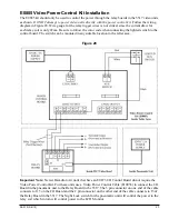
5550 (Current Style) Teller Video Unit Installation
The following instructions are for the 5550 which contains both a camera and monitor for two way
video. The 5550-1 is the same unit without a camera installed for one way video.
Installation
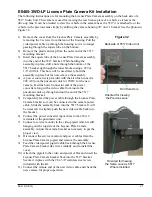
Remove the back cover from the stand by
pulling out from the top of the cover.
Tilt the video head vertical and then remove it
from the stand by removing 4 screws. Insert a
philips head screwdriver through holes in the
stand to access these screws (see Figure 20).
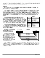
Using 75 ohm CCTV coax (Belden 1426A or
equivalent) with BNC connectors at each end,
connect the camera and monitor at the rear of
the video head (see Figure 21) to the video
matrix. Make sure to match up the audio and
video port numbers at the matrixes. For example
if the audio console is connected to Console 2 of
the audio matrix, then the video cables from that
same teller position must be connected to Console 2 of the video matrix.
Connect the supplied 12VDC power supply to the power socket on the
back of the video head (see Figure 21). If a
different power supply must be used for some
reason, it must be rated for at least 2A. The
center conductor of the 2.1mm barrel connector
is positive. Do not power this unit using the
power distribution board which was previously
used with older B5450 units. The 5550 requires
approximately 1.5A of current per unit.
With the power and video cables looped over
the top of the stand, re-connect the video head
to the stand. A choice of holes in the video head
brackets determines the overall height.
Snap the video and power cables into the cable
clamps on the back of the stand (see Figure 20).
Re-install the cover by first inserting the tabs on the bottom of the cover and then snap the top into
place.
Operation
Plug in the power supply and turn on the power switch on the bottom right side of the video head
(see Figure 22).
The height of the video head is fixed during installation. To change the height the video head must
be mounted to the stand using different mounting holes.
Tilt the video head by grasping the sides of the unit. The tilt tension is not adjustable. A swivel
mechanism is built into the base of the stand.
Use the lever next to the camera opening to tilt the camera up or down. Use the service/mirror switch
(see Figure 22) to see the camera image on the monitor. An alternate method is to press the HOLD
button on the audio console while no lane is selected. Then press HOLD again to return to normal
view.
Access holes
to remove
video head
Cable
Clamps
Power &
Video
connections
on rear of
video unit
Figure 20
Figure 21


