7
Subject to change without notice
Safety
The instrument has been designed and tested in accordance
with VDE 0411 , safety requirements for electrical equipments
for measurement, control and laboratory use. It has left the
factory wholy conform to this standard. Thus it is also in
accordance with the International standard IEC Publication
1010-1 and the European standard EN 61010-1.
The case chassis and all measuring terminals are connected to
the protective earth contact of the appliance inlet. The
instrument operates according to safety Class I (three-conductor
power cord with protective earthing conductor and a plug with
earthing contact).
CAUTION:
The mains/line plug shall only be inserted in a socket
outlet provided with a protective earth contact. The
protective action must not be negated by the use of an
extension cord without a protective conductor (or
other means).
The mains/line plug should be inserted before connections are
made to measuring circuits. Whenever it is likely that protection
has been impaired, the instrument shall be made inoperative
and be secured against any unintended operation. The
protection is likely to be impaired if, for example, the instrument
·
shows visible damage.
·
fails to perform the intended measurements.
·
has been subjected to prolonged storage under unfavourable
conditions (e.g. in the open or in moist environments).
·
has been subject to severe transport stress (e.g. in poor
packaging).
In case of leakage coming from a broken «lcd» display and
contact with skin, clean with pure water and soap . When the
metallic case is open or replaced, the instrument has to be
disconnected from the power. If measurements or calibrations
are necessary with an open instrument, they must be performed
by a qualified technician.
Operating conditions
The instrument has been designed for indoor use. The
permissible ambient temperature range during operation is
+0°C to +40°C, nevertheless refer to the technical specifications
at +23°C 2°C. It may occasionally be subjected to temperatures
-10°C without degrading its safety. The permissible ambient
temperature range for storage or transportation is -40°C to
+60°C.
The maximum operating altitude is up to 2200m. The maximum
relative humidity is up to 80%.
If condensed water exists in the instrument it should be
acclimatized before switching on . In some cases (e.g. extremely
cold) two hours should be allowed before the instrument is put
into operation. The instrument should be kept in a clean and
dry room and must not be operated in explosive, corrosive,
dusty, or moist environments. The instrument can operate in
any position, but the convection cooling must not be impaired
and the ventilation holes must not be covered.
Warranty
HAMEG warrants to its customers that the products it
manufactures and sells will be free from defects in materials
and workmanship for a period of 2 years.
This warranty shall not apply to any defect, failure or damage
caused by improper use or inadequate maintenance and
care.This warranty is limited to repair and if necessary to
replace the instrument according to the decision of HAMEG
only.
HAMEG shall not be obliged to provide service under this
warranty to repair damage resulting from attempts by personnel
other than HAMEG represantatives to install, repair, service or
modify these products. In order to obtain service under this
warranty, customers must contact and notify the distributor
who has sold the product.
Each instrument is subjected to a quality test with 24 hours
burn-in before leaving the production . Practically all early
failures are detected by this method. In the case of shipments
by post, rail or carrier it is recommended that the original
packing is carefully preserved. Transport damages and damage
due to negligence are not covered by the guarantee. In the
case of a complaint, a label should be attached to the housing
of the instrument which describes briefly the faults observed.
If at the same time the name and telephone number (dialing
code and telephone or direct number or department designation)
is stated for possible queries , this helps towards speeding up
the processing of guarantee claims.
Power requirement
The instrument is designed for a power source of 110V/220V
50Hz. The frequency and the voltage can fluctuate to 10%. An
AC power cord is supplied with the instrument. Connect it to
the power receptacle on the rear panel. Before connecting the
instrument to the power source, always make certain that the
line voltage switches on the rear panel are set to the position
corresponding to the voltage of the AC power source. The
instrument is protected by a slo-blow fuse installed in the fuse
holder.
General informations
Summary of Contents for HM8134-2
Page 1: ...Instruments MANUAL HANDBUCH MANUEL Programmable Synthesizer HM8134 2 ENGLISH...
Page 2: ...LEER...
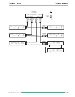
Page 21: ...21 Subject to change without notice Flowchart Menu Function selection...
Page 22: ...22 Subject to change without notice Flowchart Menu Step Control...
Page 23: ...23 Subject to change without notice Flowchart Menu Amplitude Modulation Control...
Page 24: ...24 Subject to change without notice Flowchart Menu Phase Modulation Control...
Page 25: ...25 Subject to change without notice Flowchart Menu Frequency Modulation Control...
Page 26: ...26 Subject to change without notice Flowchart Menu Gate Control...
Page 27: ...27 Subject to change without notice Flowchart Menu Main Menu Control...
Page 28: ...28 Subject to change without notice Referency loop CREF Synoptic Principal loop PLL1 134...
Page 29: ...29 Subject to change without notice Secondary loop PLL2 134 Synoptic Transposition TRA 134...
Page 31: ...31 Subject to change without notice Programmable attenuator ATP134 Synoptic...
Page 37: ...37 Subject to change without notice...
Page 38: ...38 Subject to change without notice...
Page 39: ...LEER...


