


16
Änderungen vorbehalten / Subject to change without notice
c) DC current measurement range
Ω
Ω
Ω
Ω
Ω
Ω
Ω
Ω
Ω
Ω
Ω
Ω
Test procedure
If one of the calibrators specified above or a
standard of adequate accuracy is available, all
measurement ranges of the HM8011-3 multimeter
can be checked by comparison with the limits
indicated in the following tables. If any results
deviate from the values specified in the tables, the
concerned H M 8011-3 measurement ranges must
be re-aligned. However, a re-alignment should only
be performed, if a calibrator of adequate accuracy
is available.
In all measurement ranges, the HM8011-3 test
modes must be checked by comparison with the
values specified in the following tables. However,
before changing the measurement range, care
should always be taken that the signal applied to
the HM8011-3 module does not inadmissibly stress
the device under test. At the beginning of a new
series of measurements, the calibrator should
always be reset to the minimum output value.
Before changing the measurement range, the
calibrator output must be switched off and not be
reactivated, unless the next higher HM8011-3
measurement range in order is selected. A shielded
cable should be used to connect the calibrator and
the HM8011-3 multimeter to avoid undesired
external influences on the measured signal.
For better survey, the checks should be performed
in the recommended sequence.
a) DC voltage measurement range
b) AC voltage measurement range
(1)
99.36-100.64
(2)
98.86-101.14
(1)
.9936-1.0064
(2)
.9886-1.0114
(1)
9.936-10.064
(2)
9.886-10.114
(3)
99.36-100.64
(4)
98.86-101.14
(3)
745.5-754.5
(4)
741.8-758.2
Range Ref23°C) Limits of indication
100.00mV
1.0000V
10.000V
100.00V
1000.0V
200mV
2V
20V
200V
1000V
(Tab.2)
(1)
=40Hz to 10kHz
(2)
=20Hz to 20kHz
(3)
=40Hz to 100Hz
(4)
=20Hz to 100Hz
Range Ref23°C) Limits of indication
100.00
µ
A
1.000mA
10.000mA
100.00mA
1000.0mA
1.000A
200
µ
A
2mA
20mA
200mA
2A
10A
(Tab.3)
99.78-100.22
.9978-1.0022
9.978-10.022
99.78-100.22
996.8-1003.2
0.995-1.005
Range Ref23°C) Limits of indication
100.00
µ
A
1.000mA
10.000mA
100.00mA
1000.0mA
1.000A
200
µ
A
2mA
20mA
200mA
2A
10A
(Tab.4)
99.16-100.84
.9916-1.0084
9.916-10.084
99.16-100.84
988.6-1011.4
0.988-1.011
d) AC current measurement range
e) Resistance ranges
Alignment procedure
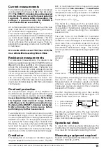
A - Clock frequency
Connect counter to 100kHz” point of testconnector CN101.
Adjust clock with
[1]
VR107 to 100 kHz ± 50 Hz.
B - Zero point DC
Select 0.2V DC range. Adjust display for zero
reading with
[2]
VC103 at open input.
C - Reference voltage
Select 2V DC range. Apply 1.8000V DC. Adjust for
a reading of 1.800V with
[3]
VR106.
D - DC voltage gain
Select 0.2V DC range. Apply 0.1 800V DC. Adjust
for a reading of 180.00 mV with
[4]
VR105.
E - Resistance reference
Select 200k
Ω
range. Connect 180k
Ω
± 0.01% or
appropriate Calibrator to input terminals. Adjust
with
[5]
VR101 for a reading of 180.00 k
Ω
.


