Connecting Internal 9V “Backup” Battery (Optional)
The internal 9V battery serves as a ‘backup’ for microSpider2 RAM. RAM is used to maintain information
such as counters, alarm state, when the modem should perform retries, and other current system
information.
Should microSpider2 lose power entirely, RAM will be lost, and on reboot the information listed above will
reset.
In the event that microSpider2 Industrial loses power (External Power In drops below 10V), the backup
battery will be used to maintain microSpider2 Industrial in a low-power mode which will maintain the RAM.
When in low-power mode, the microSpider2 will not log, and will not be accessible via LAN (even if USB
cable is connected).
To exit the low power mode and resume normal operation, either External Power of 12V or the Charger
Power of 16V must be applied to the microSpider2.
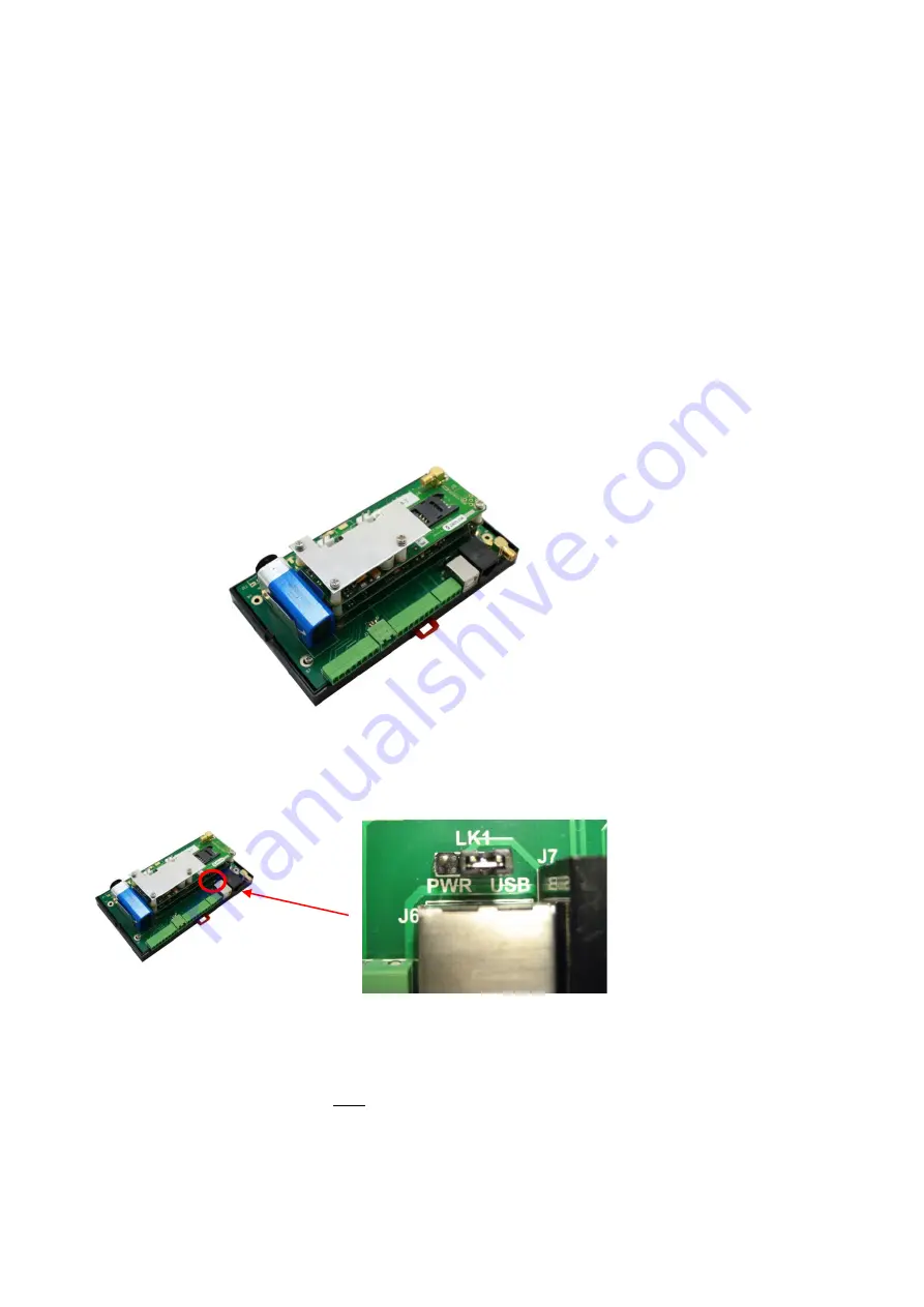
To insert the battery, open up the microSpider2 and connect a standard 9V battery to the battery clip. Insert
the battery into the metal holder
– as shown in the picture. Close up the microSpider2.
LAN Power Selector
The network (LAN) interface of the microSpider2 can operate in two different modes. Select your desired
mode by opening up the microSpider2 and inserting the black jumper as required:
“USB”
position
– This is the default position. The microSpider2 will communicate with an external computer
only if both the USB cable and the LAN cable are connected to the computer. This mode provides the lowest
possible power consumption and should always be used for battery powered installations.
“PWR”
position
– Use this position
only
for mains powered units. The LAN interface will always be powered
enabling continuous LAN communications with external PC’s, at the cost of significantly increased power
consumption. Only the LAN cable needs to be connected. This setting is suitable for industrial applications
requiring continuous LAN access.


