5
55
55
© Halstead Boilers Ltd 2008
2.0
2.0
2.0
2.0
2.0 Getting started
Getting started
Getting started
Getting started
Getting started
2.1
2.1
2.1
2.1
2.1
Before switching on
Before switching on
Before switching on
Before switching on
Before switching on
Before switching the appliance on please familiarise your-
self with:
●
how to isolate the appliance from the gas, water, and
electricity supplies;
●
how to check and top-up – if necessary – the system
water pressure;
●
the time clock or programmer;
●
any external thermostats and their functions;
●
the appliance controls.
2.2
2.2
2.2
2.2
2.2
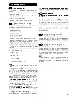
Appliance controls (see fig. 1)
Appliance controls (see fig. 1)
Appliance controls (see fig. 1)
Appliance controls (see fig. 1)
Appliance controls (see fig. 1)
The appliance controls are situated on the lower front of
the appliance. The appliance controls include:
●
pressure gauge;
●
appliance mode selector;
●
temperature selector;
●
2-digit LED display;
●
burner ON mode (green);
●
fault indicator (red);
●
optional - integral time clock/programmer (if fitted).
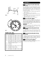
The pressure gauge shows the current pressure of your
heating system, the gauge should be set between 1 and 1.5
BAR. When the appliance is operating the gauge may rise or
fall slightly, this is quite normal. The minimum permissible
level for the safe and efficient operation of the appliance is
0.5 BAR. Should the pressure fall below 0.5 BAR, the boiler
may lockout.
The appliance mode selector is used to switch the boiler to
the various operating modes:
●
OFF/RESET “
”
●
DHW MODE ”
”
●
CH MODE “
”
●
CH with PREHEATING MODE “
”
N O
N O
N O
N O
N O TTTTTEEEEE
The appliance frost protection is active in all of the above
modes.
The temperature selectors
temperature selectors
temperature selectors
temperature selectors
temperature selectors can be used to vary the
temperature of the water that circulates around your
radiators and the water that flows from your hot water
taps. The temperature range is adjustable between 40
o
C
and 80
o
C for the central heating, and between 35
o
C and
60
o
C for the hot water. Moreover if floor heating mode is
selected (by using the relative jumper), the temperature
range for CH mode can be modified between 20°C and 45°C.
The 2-digit
2-digit
2-digit
2-digit
2-digit L
L
L
L
LED di
ED di
ED di
ED di
ED displ
spl
spl
spl
splay nor
ay nor
ay nor
ay nor
ay normally
mally
mally
mally
mally shows the operating
temperature of the appliance, however it can also display
additional characters or flashing numbers to signify specific
operating modes or fault codes.
When the status indicator (Green) is lit
status indicator (Green) is lit
status indicator (Green) is lit
status indicator (Green) is lit
status indicator (Green) is lit it indicates
that the flame is present and the burner is ON.
When the fault indicator (Red) is lit
fault indicator (Red) is lit
fault indicator (Red) is lit
fault indicator (Red) is lit
fault indicator (Red) is lit it indicates that
the appliance has identified a possible fault and performed
a safety lockout.
The integral time clock (when fitted)
integral time clock (when fitted)
integral time clock (when fitted)
integral time clock (when fitted)
integral time clock (when fitted) can be used to
switch the heating on and off at pre-determined intervals.
The integral time clock or programmer (when fitted)
integral time clock or programmer (when fitted)
integral time clock or programmer (when fitted)
integral time clock or programmer (when fitted)
integral time clock or programmer (when fitted)
can be used to switch the heating and/or hot water on and
off at pre-determined intervals.
2.3
2.3
2.3
2.3
2.3
Lighting the boiler
Lighting the boiler
Lighting the boiler
Lighting the boiler
Lighting the boiler
Ensure the gas and electrical supply to the boiler are
Ensure the gas and electrical supply to the boiler are
Ensure the gas and electrical supply to the boiler are
Ensure the gas and electrical supply to the boiler are
Ensure the gas and electrical supply to the boiler are
turned on.
turned on.
turned on.
turned on.
turned on.
Turn the mode selector switch to the ON
ON
ON
ON
ON position. When
there is a request for heating or hot water via the time clock
or programmer, the boiler will begin an ignition sequence.
When the appliance reaches the set temperature, the burner
will go off for a minimum period of approximately 3 minutes.
When the programmer/time clock or external thermostats
heating request has been satisfied, the appliance will switch
off automatically.
2.4
2.4
2.4
2.4
2.4
Adjusting the heating temperature
Adjusting the heating temperature
Adjusting the heating temperature
Adjusting the heating temperature
Adjusting the heating temperature
Rotate the temperature selector – clockwise to increase,
counter-clockwise to decrease – to the desired temperature
setting. The temperature can be set from a minimum of 40
O
C
to a maximum of 80
O
C (if standard CH mode is selected).
2.5
2.5
2.5
2.5
2.5
Adjusting the hot water temperature
Adjusting the hot water temperature
Adjusting the hot water temperature
Adjusting the hot water temperature
Adjusting the hot water temperature
Rotate the temperature selector – clockwise to increase,
counter-clockwise to decrease – to the desired temperature
setting. The temperature can be set from a minimum of 35
O
C
to a maximum of 60
O
C. If the temperature at the outlet is still
not sufficiently hot enough, it may be necessary to reduce
the flow of water at the hot water outlet (tap).
N O
N O
N O
N O
N O TTTTT EEEEE
If the appliance fails to ignite during the ignition sequence,
it will enter a lockout condition. Should this occur, please
allow a period of at least two minutes before re-setting the
appliance.


