3
33
33
© Halstead Boilers Ltd 2008
1.1
1.1
1.1
1.1
1.1
Gas appliances
Gas appliances
Gas appliances
Gas appliances
Gas appliances
Gas Safety (Installations and Use) Regulations (UK).
In the interests of your safety and that of others it is a
legal requirement that all gas appliances are installed and
correctly maintained by a competent person and in accord-
ance with the latest regulations.
1.2
1.2
1.2
1.2
1.2
Electrical supply
Electrical supply
Electrical supply
Electrical supply
Electrical supply
Please ensure that this appliance has been properly con-
nected to the electrical supply by means of a double pole
isolator or un-switched socket, and that the correct size of
fuse (3 AMP) has been fitted.
Warning: this appliance must be earthed!
1.3
1.3
1.3
1.3
1.3
Guarantee registration card
Guarantee registration card
Guarantee registration card
Guarantee registration card
Guarantee registration card
Please take the time to fill out your guarantee registration
card. The completed warranty card should be posted within
30 days of installation.
1.4
1.4
1.4
1.4
1.4
Appliance Benchmark Logbook
Appliance Benchmark Logbook
Appliance Benchmark Logbook
Appliance Benchmark Logbook
Appliance Benchmark Logbook
See rear of booklet for full terms and conditions of your
iHe
iHe
iHe
iHe
iHeaaaaattttt lifetime guarantee.
A logbook section can be found at the rear of the appliance
installation booklet. This important document must be
completed during the installation/commissioning of your
boiler. All CORGI registered installers carry a CORGI ID card,
and have a registration number. These details should be
recorded in the Benchmark logbook section within the
installation booklet. You can check your installers details
by calling CORGI direct on 01256 372300. Failure to install
and commission the appliance in accordance with the
manufacturers instructions may invalidate the warranty.
This does not affect your statutory rights.
1.5
1.5
1.5
1.5
1.5
How does it work?
How does it work?
How does it work?
How does it work?
How does it work?
Your iHe
iHe
iHe
iHe
iHeaaaaattttt boiler supplies heated water to your radiators
and hot water to your hot water taps.
The central heating is controlled via a time clock and any
thermostats that your installer may have fitted. The boiler
will light when it receives a request from the time clock via
any thermostat that may be installed, or whenever a hot
water outlet (tap) is opened.
Your iHe
iHe
iHe
iHe
iHeaaaaattttt boiler lights electronically and does not have a
pilot light.
In the unlikely event of a fault developing with your boiler,
the supply of gas to the burner will be terminated
automatically.
1.8
1.8
1.8
1.8
1.8
Frost protection system
Frost protection system
Frost protection system
Frost protection system
Frost protection system
The iHeat
iHeat
iHeat
iHeat
iHeat is equipped with a built-in frost protection
system, this enables the boiler to over-ride the time controls
– even if switched off – and operate the burner and/or
pump, should the temperature drop below 6
0
C for the main
and below 4°C for the DHW line. In particular the burner
will be in ON status until the main temperature reaches
35°C for CH appliance and 55°C for DHW appliance.
Please note that the frost protection system is
Please note that the frost protection system is
Please note that the frost protection system is
Please note that the frost protection system is
Please note that the frost protection system is
designed to protect the appliance only, should frost
designed to protect the appliance only, should frost
designed to protect the appliance only, should frost
designed to protect the appliance only, should frost
designed to protect the appliance only, should frost
protection be required for the heating system,
protection be required for the heating system,
protection be required for the heating system,
protection be required for the heating system,
protection be required for the heating system,
additional controls may be required.
additional controls may be required.
additional controls may be required.
additional controls may be required.
additional controls may be required.
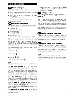
When the frost protection system has been activated, ‘AF’
‘AF’
‘AF’
‘AF’
‘AF’
is displayed on the appliance LED display (see picture).
N O
N O
N O
N O
N O TTTTT EEEEE
The frost protection system is reliant on the appliance having
a permanent electrical supply, and being in a non-fault
condition.
1.9
1.9
1.9
1.9
1.9
Appliance status indicators
Appliance status indicators
Appliance status indicators
Appliance status indicators
Appliance status indicators
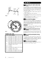
Your boiler is equipped with 2 status LED indicators, the
Green LED indicates that the flame is present, whilst the
Red LED indicates the appliance has detected a fault.
1.6
1.6
1.6
1.6
1.6
Dimensions
Dimensions
Dimensions
Dimensions
Dimensions
1.7
1.7
1.7
1.7
1.7
Clearances required
Clearances required
Clearances required
Clearances required
Clearances required
ABOVE
BELOW
LEFT SIDE
RIGHT SIDE
FRONT
150 mm
150 mm
50 mm
12mm
600 mm
iHeat25c
iHeat25c
iHeat25c
iHeat25c
iHeat25c
HEIGHT
780mm
WIDTH
400mm
DEPTH
358mm
iHeat30c - iHeat35c
iHeat30c - iHeat35c
iHeat30c - iHeat35c
iHeat30c - iHeat35c
iHeat30c - iHeat35c
HEIGHT
780mm
WIDTH
450mm
DEPTH
358mm
1.0
1.0
1.0
1.0
1.0 Things you should know
Things you should know
Things you should know
Things you should know
Things you should know


