10
OVLEREEQ*G OVLSREEQ*G OVLESREEQ*G OVLSEREEQ*G
97882C - (REV. A - 8/04)
TROUBLESHOOTING & MAINTENANCE
Orifice Assembly:
Mineral deposits on orifice can cause water
flow to spurt or not regulate. Mineral deposits may be removed
from the orifice by poking with a small round file not over 1/8
diameter, or using a small diameter wire.
DO NOT
file or cut orifice material.
Stream Regulator:
If orifice is clean, regulate flow as in Step 14
of the installation instructions. If replacement is necessary, see
parts list for correct regulator part number.
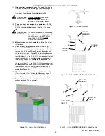
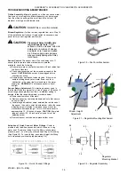
Actuation of Quick Connect Water Fittings:
Cooler is
provided with lead-free connectors which utilize an o-ring
water seal. To remove tubing from the fitting, relieve water
pressure, push in on the gray collar while pulling on the tubing
(See Figure 19). To insert tubing, push tube straight into fitting
until it reaches a positive stop (approximately 3/4).
Cleaning of Aztec Gold Models
requires special care.
Outer
surfaces must be cleaned with mild
detergent or a mixture of vinegar
and water only, rinsed and wiped
dry. Abrasive and acidic cleaners
may eventually damage the Aztec
Gold finish.
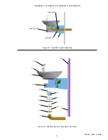
Figure 21 Regulator Mounting Mechanism
Figure 20 Push Arm Mechanism
28
14
24
15
Regulator
Mounting Bracket
43
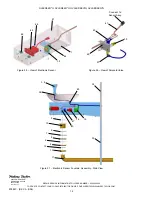
Figure 22 Regulator Assembly
19
2
20
29
30
31
23
25
27
26
Stream Height
Adjustment
Sensor Control:
The sensor has a 2 second delay time. If
sensor fails to operate valve mechanism or operates
erratically, check the following:
a) Ensure there are no obstructions within a 40 inch radius from
the front of fountain.
b) Check wire connections at the solenoid valve and at the
sensor.
CAUTION:
Make sure unit is unplugged before
checking any wiring.
c) Ensure proper operation of solenoid valve. If there is an
audible clicking sound yet no water flows, look for a
obstruction in the valve itself or elsewhere in the water
supply line.
WARNING:
Do not expose sensor to direct
sunlight.
Sensor Range Adjustment:
The electronic sensor used in
this fountain is factory pre-set for a visual range of 36 inches. If
actual range varies greatly from this, or a different setting is
desired, follow the range adjustment procedure below:
a) Remove bottom cover of fountain.
b) Remove sensor by removing washers and nuts that secure
sensor on studs.
c) Locate range adjustment screw between the red lenses of
the sensor, then with a small tip screwdriver, rotate the range
adjusting screw clockwise to increase range or counter-
clockwise to decrease range. 1/4 turn of screw is equal to
approximately 12 - 18 inches of range.
CAUTION:
Complete
range of sensor (24 - 46 inches) is only one turn of the
adjusting screw.
d) Remount sensor on studs and replace bottom cover.
Figure 19 Quick Connect Fittings
29
26


