background image

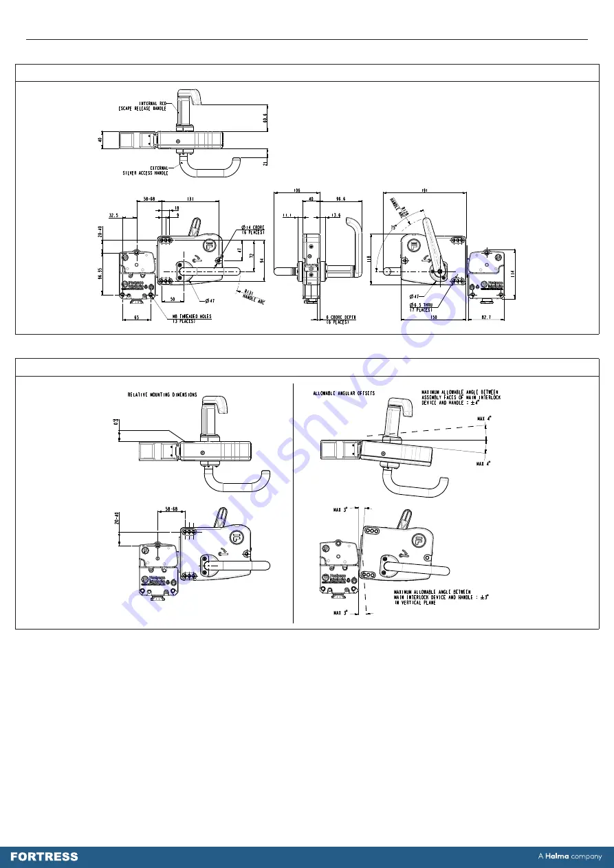
Figure 4: Mounting Drawings - amGard

pro 

Escape Release


Head and Handle

Figure 5: Mounting Drawings - amGard

pro 

Escape Release Handle Angular Offsets

FORTRESS

A               company

Halma

                www.fortressinterlocks.com

THE COPYRIGHT OF THIS DRAWING BELONGS TO FORTRESS INTERLOCKS Ltd. 

THE CONTENT OF THIS DRAWING IS CONFIDENTIAL AND MUST NOT BE 

DISCLOSED TO ANY 3rd PARTY WITHOUT SPECIFIC, WRITTEN APPROVAL.

ALL DIMENSIONS

ARE IN mm UNLESS

OTHERWISE STATED

A3

SCALE:

0.40

SHEET:

5 OF 6

ORIGINAL SIZE

DATE:

25-02-2020

ISSUE:

0

AMGARD PRO ESCAPE RELEASE HEAD AND HANDLE

DWG NO:

SD-00018

RELATIVE


MOUNTING DIMENSIONS BETWEEN I6/I7/A6/A7 ESCAPE RELEASE HEAD

AND EI/EJ ESCAPE RELEASE HANDLE

Operating Instructions: Single Action Escape Release Head & Handle 

4

FORTRESS

A               company

Halma

                www.fortressinterlocks.com

THE COPYRIGHT OF THIS DRAWING BELONGS TO FORTRESS INTERLOCKS Ltd. 

THE CONTENT OF THIS DRAWING IS CONFIDENTIAL AND MUST NOT BE 

DISCLOSED TO ANY 3rd PARTY WITHOUT SPECIFIC, WRITTEN APPROVAL.

ALL DIMENSIONS

ARE IN mm UNLESS

OTHERWISE STATED

A3

SCALE:

0.40

SHEET:

4 OF 6

ORIGINAL SIZE

DATE:

25-02-2020

ISSUE:

0

AMGARD PRO ESCAPE RELEASE HEAD AND HANDLE

DWG NO:

SD-00018

 ESCAPE RELEASE HANDLE

EI/EJ

 ESCAPE RELEASE HEAD WITH

I6/I7/A6/A7

Summary of Contents for Fortress amGardpro

Page 1: ...dle Escape Release Handle EI2 Left Escape Release Handle EI4 Right Escape Release Handle Allowing Closing of Door From Inside EJ2 Left Escape Release Handle Allowing Closing of Door From Inside EJ4 Ri...

Page 2: ...4 Prevents insertion of actuator when locked out amGardpro Escape Release Handle Safety Functions Part No Safety Function 1 Provides link from interlock to door EI EJ Safety Function 2 Internal handle...

Page 3: ...E DATE 25 02 2020 ISSUE 0 AMGARD PRO I7 A7 ESCAPE RELEASE HEAD DIMENSIONS DWG NO SD 00018 DROPDOWN LOCKOUT OPEN DROPDOWN LOCKOUT CLOSED I7 ALL IN ONE ESCAPE RELEASE HEAD WITH PADLOCKABLE DROPDOWN LOCK...

Page 4: ...GARD PRO ESCAPE RELEASE HEAD AND HANDLE DWG NO SD 00018 RELATIVE MOUNTING DIMENSIONS BETWEEN I6 I7 A6 A7 ESCAPE RELEASE HEAD AND EI EJ ESCAPE RELEASE HANDLE Operating Instructions Single Action Escape...

Page 5: ...5 1 1 Scale of Mounting Hole Positions...

Page 6: ...either by vibration or by personnel using standard tools 7 Ensure each of the three M8 head fixings are used to guarantee correct operation and maximum head retention force 8 The installation and ope...

Page 7: ...plate guard in the appropriate location Cut 3 x M6 threads into plate guard using the panel cutout dimensions given below in Figure 9 Insert red escape release handle through 50mm hole and secure hand...

Page 8: ...A7 type Head The A6 and A7 type heads require no additional resetting procedure after an escape release operation Closing the guarding door and re inserting the tongue into the head using the exterior...

Page 9: ...ns Installation and electrical connection not performed by authorised personnel Non implementation of functional checks Protection Against Environmental Influences A lasting and correct safety functio...

Reviews: