


Intrinsically safe
PP1095/2021/Issue 6
Page 2 of 8
The voltage limitation arises because of the need for safety
barriers. The barriers used with Apollo I.S. detectors are rated
at 28 volts, the highest rating that is commercially available.
These are used to limit the voltage inside the hazardous area to a
(practical) maximum of about 26 V dc. Although this is within the
standard XP95 protocol specification, it is lower than that provided
by most loop drivers.
The safety barrier is also responsible for the current limitation
because the 28 V barriers have a series resistance of at least
300 ohms. This resistance results in unacceptable voltage drops
if the normal 20 mA current pulses are used. It has therefore
been necessary to reduce the amplitude of the current
pulses to 10 mA.
XP95 Protocol Translator
In order to enable the use of standard control and indicating
equipment in intrinsically safe systems, Apollo has developed
a device to ‘translate’ voltage levels from any loop driver
operating within the XP95 limits to levels compatible with the
I.S. requirements. The translator also ‘boosts’ the current pulses
returned by the I.S. detectors from 10 mA to 20 mA, thereby
ensuring compatibility with standard loop driver thresholds. For
more information regarding the XP95 Protocol Translator refer to
PP5034.
System design
The design of an intrinsically safe fire detection system should
only be undertaken by engineers familiar with codes of practice
for detection systems and hazardous area electrical systems.
In the UK the relevant standards are BS5839-1 and BS EN 60079-
14 respectively.
The fire detection performance of the XP95 I.S. range is the same
as that of its standard counterparts. Performance information is
given in the XP95 I.S. products data sheets.
The BASEEFA certification of the I.S. devices covers their
characteristics as components of an intrinsically safe system and
indicates that they can be used with a margin of safety in such
systems. The precise way in which the system can be connected
and configured is covered by an additional, ‘system’ certification.
The System Diagram, Z20982, see Figure 6, details cable
parameters and permissible configurations of detectors, manual
call points and safety barriers which are certified by BASEEFA. Any
user wishing to install a system outside the parameters given on
this system diagram cannot make use of the Apollo certification
and should seek independent certification from a competent
certification body.
The BASEEFA system Certificate Number is BAS21Y0069 / IECEx
BAS21.0014
Any system installed within the parameters specified in Z20982
should be marked in accordance with BS EN 60079-25. The
marking should include at least ‘Apollo XP95 I.S. Fire Detection
System, BASEEFA No BAS21Y0069 / IECEx BAS21.0014
In safe area (standard) applications it will be normal practice to
connect the wiring as a loop, with both ends terminated at the
control panel. In the event of an open-circuit fault it is then possible
to drive both ends simultaneously. In a hazardous area it is not
possible to use a loop configuration because the potential to feed
power from each end of the loop would double the available energy
in the hazardous area and contravene the energy limitations of the
I.S. certification. All XP95 I.S. circuits must therefore be connected
as spurs from the safe area loop or as radial connections from the
control panel.
It is recommended, for the highest system integrity, that each I.S.
circuit be restricted to a single zone and that the connection from
the safe area loop to the I.S. spur be protected on each side by XP95
isolators. The DIN-Rail dual isolator (55000-802) is particularly
suited to this application. This configuration, shown in Figure 1 will
conform fully with the requirements of BS5839-1 and with local
codes since a single wiring fault will result in the loss of only one
zone of detection.
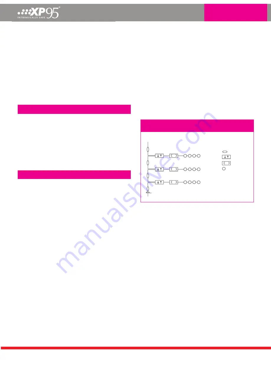
Figure 1: Schematic wiring diagram of XP95 I.S. circuit
to BS5839
XP95 Loop
in Safe Area
2 core
IS Zone n+2
IS Zone n+1
IS Zone n
Key
XP95 IS Isolator
XP95 IS Protocol Translator
Safety barrier
XP95 IS Detector
In certain circumstances it may be possible for the simpler
configuration, shown in Figure 2 to be used. This arrangement
may include single or dual-channel translators, housed, together
with the critical wiring, in a robust mechanical housing such as
the Apollo DIN-Rail enclosures part no. 29600-239 (1 x I.S. circuit)
or part no. 29600-240 (up to 5 x I.S. circuits). For further advice,
please contact the Technical Support Team at Apollo.


