6
Getting Started
Gas Connections
IM-Series mass flow controllers/meters do not require straight runs of pipe upstream or
downstream.
Devices ship with plastic plugs seated in the processing ports. To decrease the chance of
contaminating the flow stream, do not remove these plugs until you are ready to install
the device.
After removing the plugs, immediately connect the device to upstream and downstream
plumbing, leak-tight. Verify that the flow matches the direction indicated on the device
body. Standard gas flow controllers/meters have female inlet and outlet ports. Options
for connections include NPT, SAE, BSPP, and VCR
®
-compatible (some of these fittings may
have male connections).
If you are using a fitting that does not have a face seal, use thread-sealing Teflon tape to
prevent leakage around the port threads,
but
do not wrap the first two threads entering
the device. This will minimize the possibility of tape entering the flow stream and clogging
the laminar flow elements.
Face seal fittings can be installed without Teflon tape applied to the threads.
∆
Caution:
Pipe dopes or sealants are not recommended on the process connections.
These compounds can cause permanent damage to the controller should they get into
the flow stream.
Maximum Pressure
The maximum common mode pressure is
200
PSIA
. Common mode pressure is the
maximum pressure that may be applied simultaneously to both sides of the instrument
without causing damage.
!
Warning:
Using the flow controller above the maximum specified common pressure
will permanently damage the internal pressure sensors. If the line pressure is above
these limits, use a pressure regulator upstream of the device to reduce the pressure
below 200 PSIA
.
Maximum Flow
The maximum flow is 25 times the full-scale flow rating of the instrument. Exceeding this
may cause permanent damage to the internal differential pressure sensor.
Commanding a non-zero setpoint prior to applying the pressure will cause the valve to be
fully open and will expose the sensor to any instantaneous changes in pressure, such as
from a snap-acting solenoid valve. For meters and controllers with downstream valves,
install a flow restriction upstream of the device to limit large, instantaneous changes in
pressure.
Power and Signal Connections
Power is supplied to the controller through the DB9 connector on the top of the device.
The table below indicates how to connect the device to power and communication. If your
device was built with a different configuration, please refer to the corresponding pinout
found at
The device power requirement for Factory OEM mass flow devices is: 12–24 VDC, 250 mA
for the standard device, or 290 mA if equipped with 4–20 mA output.
!
Warning:
Do not power the device until all necessary pins have been properly
connected.
!
Warning:
Only connect power to pin 7. Connecting power to other pins can permanently
damage the device.
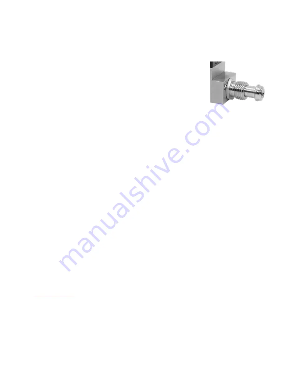
A mass flow controller with male
VCR®-compatible connections.


