14
Digital controllers with off cycle defrost, AUX relay,
power supply 100 or 230VAC with or w/out battery
backup.
XR30CX
REF. 0-7020115, 0-7020110, 0-7020122, 0-7020202, 7020346.
1.
GENERAL WARNING
1.1
PLEASE READ BEFORE USING THIS MANUAL
This manual is part of the product and should be kept near the instrument for easy and quick
reference.
The instrument shall not be used for purposes different from those described hereunder. It
cannot be used as a safety device.
Check the application limits before proceeding.
3
.
MAX & MIN TEMPERATURE MEMORIZATION
3
.1
HOW TO SEE THE MIN TEMPERATURE
1.
Press and release the DOWN button.
2.
The “Lo” message will be displayed followed by the minimum temperature recorded.
3.
By pressing the DOWN button again or by waiting for 5s the normal display will be restored.
3
.2
HOW TO SEE THE MAX TEMPERATURE
1.
Press and release the UP button.
2.
The “Hi” message will be displayed, followed by the maximum recorded temperature.
3.
By pressing the UP button again or by waiting for 5s, the normal display will be restored.
3
.3
HOW TO RESET THE MAX AND MIN TEMPERATURE RECORDED
1.
Keep SET button pressed more than 3s while the max or min temperature is displayed
(“rSt” message will be displayed).
2.
To confirm the operation the “rSt” message starts blinking and the normal temperature will be
displayed.
2
.
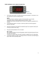
FRONT PANEL COMMANDS
To display target set point.
In programming mode it selects a parameter or confirm an operation.
(DEF) To start a manual defrost.
(UP) To see the max stored temperature. In programming mode it browses
parameters or increases the displayed value.
(DOWN) To see the min stored temperature. In programming mode it
browses the parameters or decreases the displayed value.
To switch the instrument on and off when onF=oFF.
NOT USED
+
To lock & unlock the keyboard.
2
.1
USE OF LEDS
Each LED function is described in the following table.
LED
MODE
FUNCTION
ON
Compressor enabled
Flashing
Anti-short cycle delay enabled
ON
Defrost enabled
ON
An alarm is occurring
ON
Continuous cycle is running
ON
Energy saving enabled
°C/°F
ON
Measurement unit
Flashing
Programming phase
4
.
MAIN FUNCTIONS
4
.1
HOW TO SEE THE SETPOINT
1.
Push and immediately release the SET button: the display will show the
Set point value;
2.
Push and immediately release the SET button or wait for 5 seconds to
display the probe value again.
4
.2
HOW TO CHANGE THE SETPOINT
1.
Keep SET button pressed more than 2 seconds to change the Set point value.
2.
The value of the set point will be displayed and the “°C” or “°F” LED icon will start blinking.
3.
To change the Set-point value, push the UP or DONW buttons within 10s.
4.
To memorise the new set point value, push the SET button again or wait for 10s.
4
.
3
HOW TO LOCK THE KEYBOARD
1.
Keep pressed for more than 3 s the UP + DOWN buttons.
2.
The “PoF” message will be displayed and the keyboard will be locked. At this point it will be
possible only to see the set point or the MAX o Min temperature stored
3.
If a button is pressed more than 3s the “PoF” message will be displayed.
4
.
4
TO UNLOCK THE KEYBOARD
Keep pressed both UP and DOWN for more than 3s till the “Pon” message will be displayed.
4
.
5
THE ON/OFF FUNCTION
When “onF=oFF”, pushing the ON/OFF key, the instrument is switched off. The “OFF”
message is displayed. In this configuration, the regulation is disabled.
To switch the instrument on, push again the ON/OFF key.
WARNING: Loads connected to the normally closed contacts of the relays are always
supplied and under voltage, even if the instrument is in stand by mode.
5
.
PARAMETERS
REGULATION
LS
Minimum set point: (-100°C÷SET; -148°F÷SET) it sets the minimum value for the
set point.
US
Maximum set point: (SET÷150°C; SET÷302°F) it sets the maximum value for set
point.
temperature is given by the ALL or ALU values. rE = temperature alarms are referred
to the set point. Temperature alarm is enabled when the temperature exceeds the
[SET+ALU] or [SET-ALL] values.
ALU
MAXIMUM temperature alarm:
ALC=Ab: (SET÷150°C; SET÷302°F)
ALC=rE: (0.1÷50°C; 1÷90°F)
When this temperature is reached, the alarm is enabled, possibly the ALd delay
time.
ALL
Minimum temperature alarm:
ALC=Ab: (-100.0 ÷ SET°C; -148÷302°F)
ALC=rE: (0.1÷50°C; 1÷90°F)
When this temperature is reached, the alarm is enabled, possibly the ALd delay time.
AFH
Differential for temperature alarm recovery: (0.1÷25.5°C; 1÷45°F) intervention
differential for recovery of temperature alarm.
ALd
Temperature alarm delay: (0÷255 min) time interval between the detection of an
alarm condition and alarm signalling.
dAo
Exclusion of temperature alarm at start-up: (0.0÷23h 50min, res. 10min) time
interval between the detection of the temperature alarm condition after instrument
power on and alarm signalling.
ALARM RELAY MANAGEMENT –FOR BATTERY-BACKUP MODELS (7020122 and 7020202)
tbA
Alarm relay silencing (with oA1=ALr): (n, Y)
n = silencing disabled; alarm relay stays on till alarm condition lasts.
Y = silencing enabled; alarm relay is switched OFF by pressing a key during an
alarm.
Aro
Alarm relay activation with power failure: (n, Y)
n = the alarm relay is never activated during a power failure.
Y = the alarm relay is activated during a power failure.
ALF
Alarm relay activation for all the alarms: (n, Y)
n = the alarm relay is activated only in case of a temperature alarm or regulation
probe failure.
Y = the alarm relay is activated for all the alarms.
bon
Time of buzzer restart after muting, in case of alarm duration: (0÷30min) when
0 the buzzer is always off after muting.
AoP
Alarm relay polarity: it set if the alarm relay is open or closed when an alarm
happens. CL= terminals 1-2 closed during an alarm; oP = terminals 1-2 open during
an alarm
DIGITAL INPUT
i1P
Digital input polarity: (oP; CL) oP = the digital input is activated by opening the
contact; CL = the digital input is activated by closing the contact.
i1F
Digital input configuration: (EAL; bAL; PAL; dor; dEF; AUS; Htr; FAn; ES)
EAL = external alarm: “EA” message is displayed; bAL = serious alarm “CA”
message is displayed. PAL = pressure switch alarm, “CA” message is displayed; dor
= door switch function; dEF = activation of a defrost cycle; AUS =to switch on the
second relay if oA1 = AUS; Htr = kind of action inversion (cooling – heating); FAn =
not set it; ES = Energy saving.
6
.
ALARM
MESSAGES
6
.
1
OTHER MESSAGES
Pon Keyboard unlocked.
PoF Keyboard locked
7
.
TECHNICAL DATA
Housing: self extinguishing ABS.
Case: XR30CX frontal 32x74mm; depth 60mm.
Mounting: XR30CX panel mounting in a 71x29mm panel cut-out.
Protection: IP20. Frontal protection: XR30CX IP65.
Connections: Screw terminal block
2.5 mm
2
wiring.
Model 7020346 and 7020345: fast-on tabs 6,3mm for loads and power supply; Disconnect able
screw terminal blocks for probe, digital input and
Power supply: according to the model: 100Vac
10%, 50/60Hz; or 230Vac
10%, 50/60Hz, or
120Vac
10%, 50/60Hz, or
Power absorption: 3VA max.
Display: 3 digits red LEDs, 14.2 mm high.
Digital input: free voltage contact.
Analogue Input: a PT1000 or PTC probe, set via parameter.
Relay outputs:
Compressor: 20(8)A, 250Vac.
Alarm: SPDT 8(3)A, 250Vac.
Connectors for external backup battery (only for battery-backup model).
Data storing: on the non-volatile memory (EEPROM).
Kind of action: 1B. Pollution degree: 2. Software class: A.
Rated impulsive voltage: 2500V. Overvoltage Category: II.
Operating temperature: 0÷60°C.
Storage temperature: -30÷85 °C.
Relative humidity: 20
85% (no condensing).
Measuring and regulation range:
Pt1000 probe: -100÷100°C (-148÷212°F).
PTC probe: -55÷150°C (-67÷302°F).
Resolution: 0.1°C or 1°C or 1°F (selectable).
Accuracy (ambient temp. 25°C): ±0.7 °C ±1 digit.
Only for battery backup model:
Type of battery: 6Vdc, 1.2Ah.
Charging time: 94hours.

