background image


UH2X-P1


HDBASET 

Connect to the transmitter unit with a single CAT5e/6/7 cable for transmission of all 

data signals. The yellow LED will illuminate if the link from receiver is steady, 

when it blinks irregularly it represents that there is a link error and when there is no 

illumination, it means that there is no link with the receiver. The green LED will 

illuminate to represent the HDMI signal with HDCP encryption. 

POWER  

Indicates that the receiver is powered ON. 


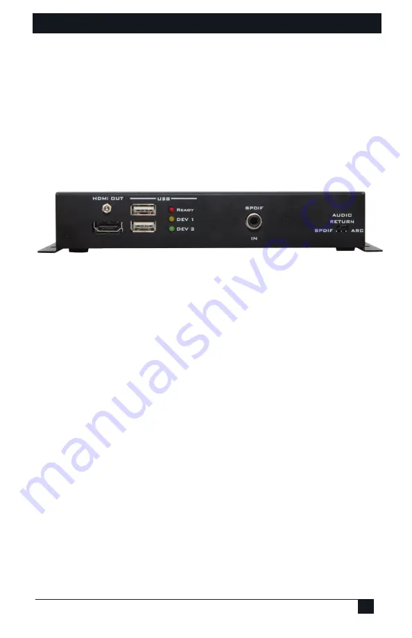
4.4 Receiver’s Rear Panel 


HDMI OUT 

Connect to a HDMI equipped TV/monitor for display of the HDMI input source 

signal.  

USB  

Connect to USB peripheral devices such as printer, keyboard, flash driver…etc. for 

data receiving or sending back to Transmitter.  

READY 

This LED will be illuminated when a link is setup between the Sender and Receiver 

enabling USB device usage. 

DEV 1 

This LED glows when the upper USB slot is connected with a device signal 

activated.   

DEV 2 

It represents that the lower USB slot is connected with a device signal activated. 

SPDIF IN 

Connect to audio source such as the TV's digital output, or any audio equipment with 

digital audio output. If selected, this signal will be routed to the Transmitter. 

Audio Return Switch 

This switch selects between the HDMI ARC channel from the TV or the SPDIF 

input audio (see section 4.6 for more details). 


Summary of Contents for UH2X-P1

Page 1: ...uncompressed video to 100 meters Also Extends USB LAN RS232 and IR Sender powers Receiver via UTP using PoH Supports 4K resolution UMA1237 Rev n c Copyright 2015 Hall Research Inc All rights reserved 1163 Warner Ave Tustin CA 92780 Ph 714 641 6607 Fax 714 641 6698 ...

Page 2: ...NCY INTERFERENCE STATEMENT This equipment generates uses and can radiate radio frequency energy and if not installed and used properly that is in strict accordance with the manufacturer s instructions may cause interference to radio communication It has been designed to comply with the limits for a Class A computing device in accordance with the specifications in Subpart B of Part 15 of FCC rules ...

Page 3: ...80p 60 3D and deep color to 100m resolutions to 4Kx2K UHD up to 60m Extends USB 2 0 and has integrated 2 port Hub in the Receiver Perfect for KVM extension Extends Ethernet 100BaseT bi directional IR and RS232 control signals Front panel LED indicators for status monitoring Plug and play installation takes minutes to setup Supports pass through of HDMI embedded audio formats LPCM 2 5 1 7 1 Channel...

Page 4: ...HDMI USB LAN Sender and Receiver 4 3 0 Installation The following diagram illustrates a typical setup Installation diagram showing all possible connections Product footprint and mounting hole positions ...

Page 5: ...e product is Plug n Play meaning that when connected as described in the previous section there are no additional settings required 4 1 Transmitter s Front Panel RS 232 Pin 2 TX Pin 3 RX Pin 5 GND Use a straight thru DB9 M F cable to connect this port to your Pc or USB to RS232 adapter IR IN Connect the supplied IR detector cable for IR signal reception IR OUT Connect to the supplied IR Emitter Ca...

Page 6: ... the SPDIF connector on the receiver or the ARC pin of the HDMI Output user selectable This signal can be 2 channel PCM or multi channel Dolby or DTS The UH2X passes this signal from the Receiver to the Sender just as is without any modification If you need convert it to analog use Hall Research s DAC 51 4 3 Receiver s Front Panel RS 232 Connect to the device that has to be controlled Pin 2 RX Pin...

Page 7: ...HDMI input source signal USB Connect to USB peripheral devices such as printer keyboard flash driver etc for data receiving or sending back to Transmitter READY This LED will be illuminated when a link is setup between the Sender and Receiver enabling USB device usage DEV 1 This LED glows when the upper USB slot is connected with a device signal activated DEV 2 It represents that the lower USB slo...

Page 8: ... Data Connection Baud Rate 300 115200bps 4 6 ARC Switch The user has the option to select the audio from either the Audio Return Channel ARC or the Digital audio input that s in turn available at the SPDIF OUT at the sender Audio Return Channel Routing Block Diagram ...

Page 9: ...n 2 1 Replacement cable Hall Research P N CIR DET P2 Tip Data Ring 5V Sleeve Gnd Note This is a representative image The actual cable may look slightly different Do not substitute any other emitter or detector cable as this may not work the extenders as well as your substitute IR cable may also get damaged One IR emitter cable is provided with the extender kit per Section 2 1 Replacement Hall Rese...

Page 10: ...ll Research Technical Support at 714 641 6607 or support hallresearch com Before you do make a record of the history of the problem We will be able to provide more efficient and accurate assistance if you have a complete description 5 2 Shipping and Packaging If you need to transport or ship your unit Package it carefully We recommend that you use the original container Before you ship the units b...

Page 11: ...1 x SPDIF Receiver Input Ports Output Ports LAN Power Supply 1 x HDBaseT 1 x IR 1 x SPDIF 1 x HDMI 1 x RS232 1 x IR 2 x USB Bidirectional 110 120V AC 50 60 Hz 48 VDC 0 83A US EU Standard CE FCC UL Certified ESD Protection Human Body model 8kV air gap discharge 4kV contact discharge Dimensions 7 3 185mm W x 5 1 130mm D x 1 3 33mm H All protrusions included Weight Shipping 4 05 lbs 1 84kg with power...

Page 12: ...UH2X P1 Copyright 2015 Hall Research Inc All rights reserved 1163 Warner Ave Tustin CA 92780 Ph 714 641 6607 ...

Reviews: