Reassembly
1.
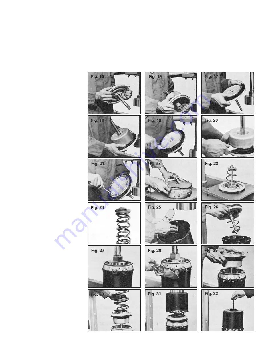
Install service piston bearing such
that concave portion of the bearing
provides support for packing cup and all
tabs are snapped over piston flange
(Fig. 15). Properly seat packing cup
(Fig. 17).
2.
(Packing Cup Emergency Piston)
Install piston bearing and packing cup as
described in Step 1 (Fig. 16 & 18).
(O-Ring Emergency Piston)
Assemble piston bearing with tab seated
in O-ring groove and positioned over
piston flange facing open end. Pack
O-ring groove and completely cover
O-ring with supplied lubricant. Install
O-ring, (skip 3, 4, 5 below).
3.
Sealing surfaces on packing cups
and piston must be free of all dust,
grease and oil. Apply sealing compound
to service piston (Fig. 19) and, if
applicable, emergency piston (Fig. 20).
Smooth beads between inner lip of
packing ring and piston. MAKE SURE
NO COMPOUND IS ON OUTER LIP.
Install retainer ring and self-tapping
screws.
4.
The sealing surfaces must be free of
all dust, grease and oil. Apply the sealing
compound to the service piston (Fig. 19)
and emergency piston (Fig. 20). Smooth
the beads of sealing compound. The
compound seals the inner lip of the
packing cup to the piston. Make sure
there is no compound on the outer lip.
5.
Install retainer ring and self-tapping
screws on service piston (Fig. 21) and
allow the compound beneath the retainer
ring to set for at least eight hours before
assembling the piston into the cylinder.
6.
Lubricate the large seal grooves of
the center boss with supplied lubricant
and install the small O-ring, nylon
bushing and snap ring in the middle of
the unit. Be sure the flat flange surface
of the bushing contacts the O-ring.
Install the two larger O-rings in the outer
seal grooves of the bulkhead (Fig. 22).
7.
Compress the return spring on the
service piston. Make sure the large
diameter of the spring is toward the
piston. Install the return spring locator
and jam nut (Fig. 23).
8.
Insert the booster spring into the
heavy spring and align the coil ends so
they are 180º opposite. Place the spring
locator on the springs and the new filter
over the hole in the locator (Fig. 24).
9.
Lubricate the bores of the service
and emergency cylinders with supplied
lubricant (Fig. 25).
10.
Place the service cylinder in the
press and install the service piston
assembly (Fig. 26). Make sure the jam
nut centers on the push rod hole of the
cylinder.
11.
Place the bulkhead with the
concave side up, into the service
cylinder. Press together (Fig. 27),
aligning the cap screw holes, and install
the cap screws (Fig. 28) at 100 in.-lbs.
(8.3 ft.-lbs) to 125 in.-lbs. (10.9 ft.-lbs.)
torque. NOTE: Over tightening can
cause the cap screw threads to strip.
12.
Place the emergency piston with
the piston rod into the center boss
(Fig. 29).
13.
Place the springs, locator and
filter into the emergency piston (Fig. 30).
14.
Place the emergency cylinder over
the springs. Make sure the spring
locator and filter are centered in the
cylinder.
15.
Press the emergency cylinder
down to the bulkhead (Fig. 31). Align
the cap screw holes and install the cap
screws securely with the same torque as
used in Step 11.
16.
Apply air pressure to the
emergency inlet and install the release
bolt and washer (Fig. 32).
17.
Remount the unit on the vehicle.
Be sure the service filter is replaced with
the new one furnished in the
service kit. Also, make sure the rubber
plug is pressed into the release bolt hole
after the bolt is removed. This plug
prevents contaminants from entering
through an unfiltered passage.
18.
Adjust brakes per vehicle
specifications so the stroke of the
actuator is as short as possible and the
shoes do not drag. The brake adjuster
should be approximately 90º to the push
rod when brakes are fully applied and
adjusted.
19.
Test the brake operation before
removing wheel blocks.


